PARKING ASSIST MONITOR SYSTEM(for Camera built-in ECU) TERMINALS OF ECU
CHECK TELEVISION CAMERA ASSEMBLY
-
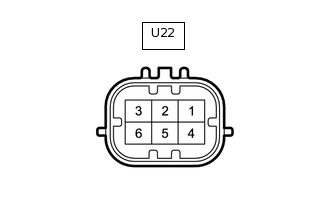
Disconnect the U22 television camera assembly.
Measure the voltage and resistance according to the value(s) in the table below.
Terminal No. (Symbol)
Wiring Color
Terminal Description
Condition
Specified Condition
U22-6 (CB+) - Body ground
B - Body ground
Power source
Ignition switch ACC
5.5 to 7.05 V
U22-5 (CGND) - Body ground
BR - Body ground
Ground
Always
Below 1 Ω
Reconnect the U22 television camera assembly connector.
Check for pulses between each terminal of the connector.
Terminal No. (Symbol)
Wiring Color
Terminal Description
Condition
Specified Condition
U22-3 (CV+) - U22-2 (CV-)
W - R
Video signal
Ignition switch ON, camera lens not covered, displaying an image
Pulse generation (See waveform 1)
Ignition switch ON, camera lens covered, blacking out screen
Pulse generation (See waveform 2)
Tip:A waterproof connector is used for the television camera assembly. Therefore, inspect the waveform at the navigation receiver assembly*1 or radio and display receiver assembly*2 with the connector connected. If the result is not as specified, the television camera assembly may have a malfunction.
*1: for Navigation Receiver Type
*2: for Radio and Display Type
-
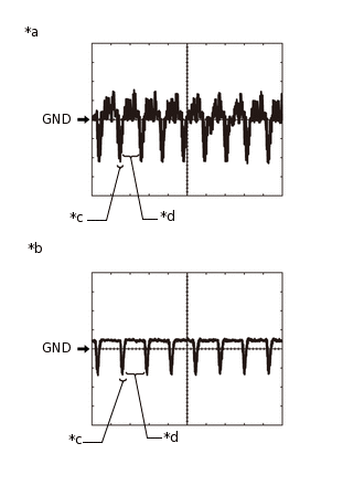
*a
Waveform 1
*b
Waveform 2
*c
Synchronized Signal
*d
Video Waveform
Reference (Oscilloscope waveform):
Tip:A waterproof connector is used for the television camera assembly. Therefore, inspect the waveform at the navigation receiver assembly*1 or radio and display receiver assembly*2 with the connector connected.
*1: for Navigation Receiver Type
*2: for Radio and Display Type
Waveform 1
Item
Content
Terminal No. (Symbol)
U22-3 (CV+) - U22-5 (CGND)
Tool Setting
200 mV/DIV., 50 μsec./DIV.
Condition
Ignition switch ON, camera lens not covered, displaying an image
Tip:The video waveform changes according to the image sent by the television camera assembly.
Waveform 2
Item
Content
Terminal No. (Symbol)
U22-3 (CV+) - U22-5 (CGND)
Tool Setting
200 mV/DIV., 50 μsec./DIV.
Condition
Ignition switch ON, camera lens covered, blacking out screen
Tip:The video waveform changes according to the image sent by the television camera assembly.
-
CHECK NAVIGATION RECEIVER ASSEMBLY (for Navigation Receiver Type)

Check for resistance, voltage and waveform between each terminal of the connector.
Terminal No. (Symbol)
Wiring Color
Terminal Description
Condition
Specified Condition
G139-2 (REV) - G137-7 (GND1)
BE - BR
Reverse signal
See "Vehicle Signal Check Mode" in Operation Check
-
G158-11 (CA+) - G158-23 (CGND)
B - Shielded
Television camera assembly power supply
Ignition switch ACC
5.5 to 7.05 V
G158-12 (V+) - G158-23 (CGND)
W - Shielded
Video signal
Ignition switch ON, camera lens not covered, displaying an image
Pulse generation (See waveform 1)
Ignition switch ON, camera lens covered, blacking out screen
Pulse generation (See waveform 2)
G158-24 (V-) - G158-23 (CGND)
R - Shielded
Ground
Always
Below 1 Ω
Tip:A waterproof connector is used for the television camera assembly. Therefore, inspect the waveform at the navigation receiver assembly with the connector connected. If the result is not as specified, the television camera assembly may have a malfunction.
-
*a
Waveform 1
*b
Waveform 2
*c
Synchronized Signal
*d
Video Waveform
Reference (Oscilloscope waveform):
Tip:A waterproof connector is used for the television camera assembly. Therefore, inspect the waveform at the navigation receiver assembly with the connector connected.
Waveform
Item
Content
Terminal No. (Symbol)
G158-12 (V+) - G158-23 (CGND)
Tool Setting
200 mV/DIV., 50 μsec./DIV.
Condition
Waveform 1: Ignition switch ON, camera lens not covered, displaying an image
Waveform 2: Ignition switch ON, camera lens covered, blacking out the screen
Tip:The video waveform changes according to the image sent by the television camera assembly.
-
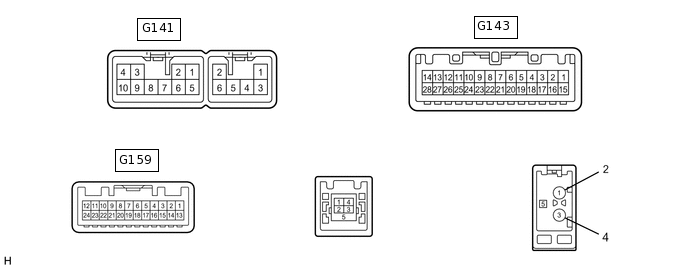
CHECK RADIO AND DISPLAY RECEIVER ASSEMBLY (for Radio and Display Type)
Check for resistance, voltage and waveform between each terminal of the connector.
Terminal No. (Symbol)
Wiring Color
Terminal Description
Condition
Specified Condition
G143-2 (REV) - G141-7 (GND1)
BE - BR
Reverse signal
See "Vehicle Signal Check Mode" in Operation Check
-
G159-11 (CA+) - G159-23 (CGND)
B - Shielded
Television camera assembly power supply
Ignition switch ACC
5.5 to 7.05 V
G159-12 (V+) - G159-23 (CGND)
W - Shielded
Video signal
Ignition switch ON, camera lens not covered, displaying an image
Pulse generation (See waveform 1)
Ignition switch ON, camera lens covered, blacking out screen
Pulse generation (See waveform 2)
G159-24 (V-) - G159-23 (CGND)
R - Shielded
Ground
Always
Below 1 Ω
Tip:A waterproof connector is used for the television camera assembly. Therefore, inspect the waveform at the radio and display receiver assembly with the connector connected. If the result is not as specified, the television camera assembly may have a malfunction.
-
*a
Waveform 1
*b
Waveform 2
*c
Synchronized Signal
*d
Video Waveform
Reference (Oscilloscope waveform):
Tip:A waterproof connector is used for the television camera assembly. Therefore, inspect the waveform at the radio and display receiver assembly with the connector connected.
Waveform
Item
Content
Terminal No. (Symbol)
G159-12 (V+) - G159-23 (CGND)
Tool Setting
200 mV/DIV., 50 μsec./DIV.
Condition
Waveform 1: Ignition switch ON, camera lens not covered, displaying an image
Waveform 2: Ignition switch ON, camera lens covered, blacking out the screen
Tip:The video waveform changes according to the image sent by the television camera assembly.