AIR CONDITIONING UNIT REMOVAL
PROCEDURE
-
PRECAUTION
Note
Make sure to select DEF mode before disconnecting the cable from the negative (-) auxiliary battery terminal.
-
RECOVER REFRIGERANT FROM REFRIGERATION SYSTEM (for HFC-134a(R134a))
-
RECOVER REFRIGERANT FROM REFRIGERATION SYSTEM (for HFO-1234yf(R1234yf))
-
REMOVE WINDSHIELD WIPER MOTOR AND LINK
-
REMOVE COWL BODY MOUNTING REINFORCEMENT LH (for LHD)
-
REMOVE OUTER COWL TOP PANEL SUB-ASSEMBLY (for LHD)
-
REMOVE COWL BODY MOUNTING REINFORCEMENT RH (for RHD)
-
REMOVE OUTER COWL TOP PANEL SUB-ASSEMBLY (for RHD)
-
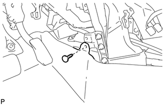
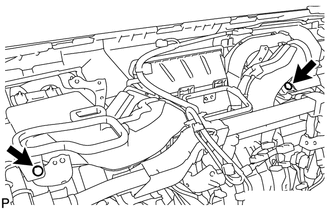
DISCONNECT SUCTION PIPE SUB-ASSEMBLY
-
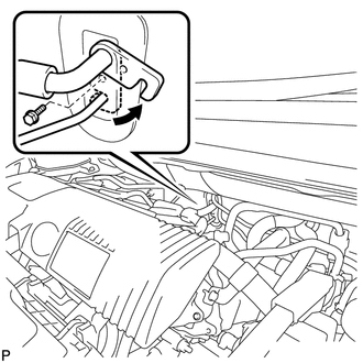
Remove the bolt and slide the hook connector.
-
Disconnect the suction pipe sub-assembly.
-
Remove the O-ring from the suction pipe sub-assembly.
Note
Seal the openings of the disconnected parts using vinyl tape to prevent entry of moisture and foreign matter.
-
-
DISCONNECT AIR CONDITIONER TUBE AND ACCESSORY ASSEMBLY
-
Disconnect the air conditioner tube and accessory assembly.
-
Remove the O-ring from the air conditioner tube and accessory assembly.
Note
Seal the openings of the disconnected parts using vinyl tape to prevent entry of moisture and foreign matter.
-
-
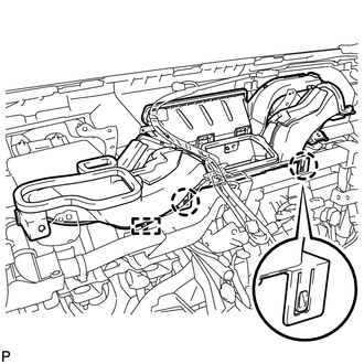
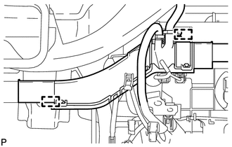
DISCONNECT INLET HEATER WATER HOSE A
-
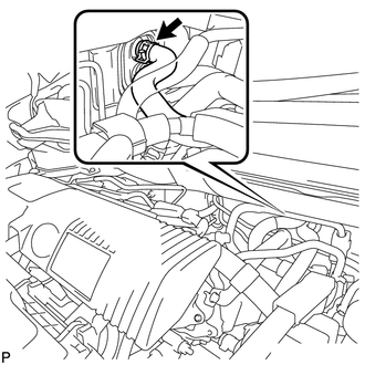
Using pliers, grip the claws of the clip and slide the clip to disconnect the inlet heater water hose A.
Note
-
Do not apply excessive force to the inlet heater water hose A.
-
Prepare a drain pan or cloth in case the coolant leaks.
-
-
-
DISCONNECT OUTLET HEATER WATER HOSE A
-
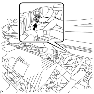
Using pliers, grip the claws of the clip and slide the clip to disconnect the outlet heater water hose A.
Note
-
Do not apply excessive force to the outlet heater water hose A.
-
Prepare a drain pan or cloth in case the coolant leaks.
-
-
-
REMOVE LOWER INSTRUMENT PANEL SUB-ASSEMBLY
-
REMOVE STEERING POST ASSEMBLY
-
REMOVE ECU INTEGRATION BOX RH (for LHD)
-
REMOVE ECU INTEGRATION BOX LH (for RHD)
-
REMOVE ECU INTEGRATION BOX RH (for RHD)
-
REMOVE INSTRUMENT PANEL JUNCTION BLOCK ASSEMBLY
-
REMOVE WINDSHIELD WIPER RELAY ASSEMBLY (w/ Rain Sensor)
-
REMOVE CENTER INSTRUMENT PANEL REINFORCEMENT SUB-ASSEMBLY
-
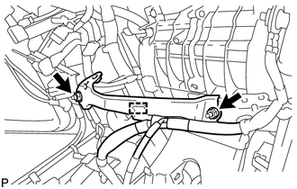
Disengage the clamp.
-
Remove the 2 nuts and center instrument panel reinforcement sub-assembly.
-
-
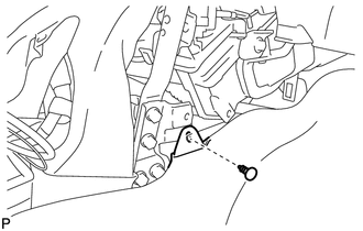
REMOVE COOLER THERMISTOR (ROOM TEMPERATURE SENSOR)
-
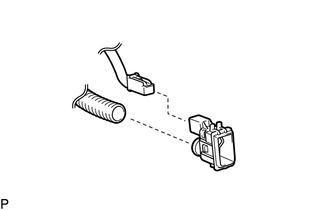
Disconnect the aspirator and connector, and remove the cooler thermistor (room temperature sensor).
-
-
REMOVE NO. 2 INSTRUMENT PANEL MOUNTING BRACKET
-
Using a clip remover, remove the clip and turn back the floor carpet.
-
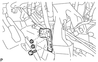
Remove the bolt and 2 nuts, and No. 2 instrument panel mounting bracket.
-
-
REMOVE NO. 1 INSTRUMENT PANEL BRACE SUB-ASSEMBLY
-
Disengage the 4 clamps.
-
Remove the screw, nut, and No. 1 instrument panel brace sub-assembly.
-
-
REMOVE NO. 1 INSTRUMENT PANEL MOUNTING BRACKET
-
Using a clip remover, remove the clip and turn back the floor carpet.
-
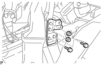
Remove the 2 bolts, 2 nuts, and No. 1 instrument panel mounting bracket.
-
-
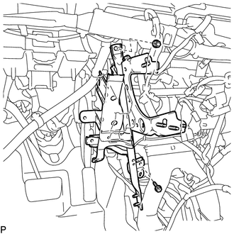
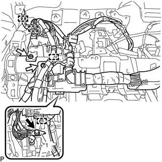
REMOVE NO. 2 INSTRUMENT PANEL BRACE SUB-ASSEMBLY
-
Text in Illustration *1 Earth Wire Remove the bolt and disconnect the earth wire.
-
Remove the bolt.
-
Disengage the clamp.
-
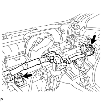
Remove the 2 bolts.
-
Disengage the 3 clamps.
-
Text in Illustration *1 Earth Wire Remove the bolt and disconnect the earth wire.
-
Disengage the 3 clamps.
-
Remove the screw, nut, and No. 2 instrument panel brace sub-assembly.
-
-
REMOVE LOWER DEFROSTER NOZZLE ASSEMBLY
-
Disengage the 2 clamps.
-
Using a clip remover, remove the 2 clips.
-
Disengage the 2 claws and guide, and remove the lower defroster nozzle assembly.
-
-
REMOVE REAR NO. 1 AIR DUCT
-
Disengage the clamp.
-
Disengage the 8 claws and remove the rear No. 1 air duct.
-
-
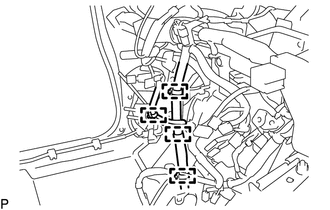
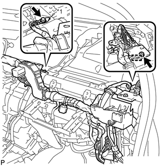
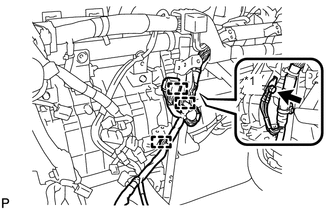
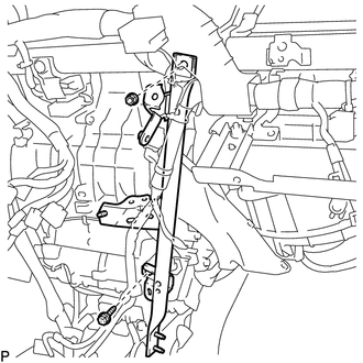
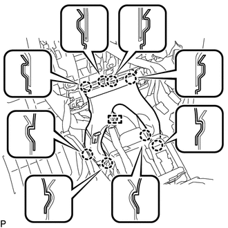
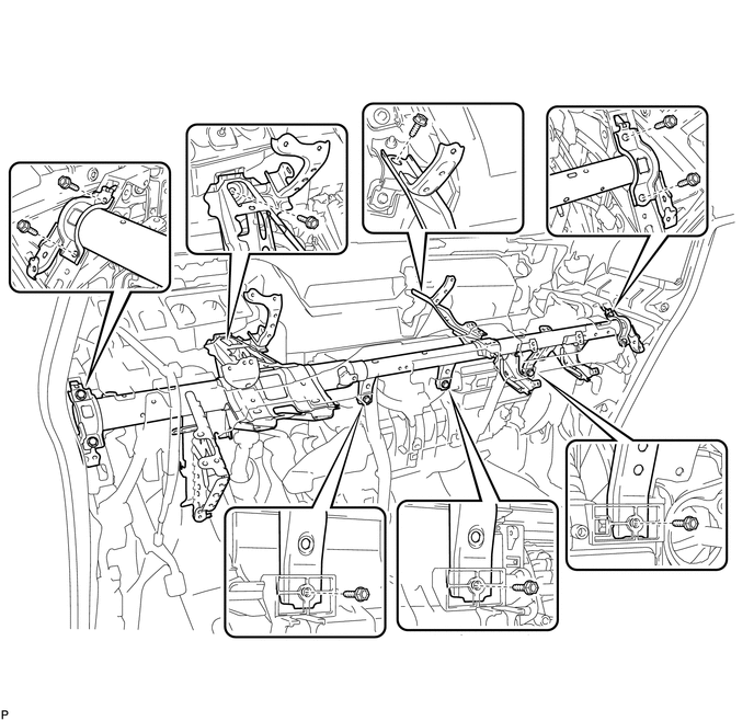
REMOVE INSTRUMENT PANEL REINFORCEMENT ASSEMBLY
-
Remove the bolt.
-
Disengage the 3 clamps.
-
Disengage the 2 clamps.
-
Text in Illustration *1 Earth Wire Remove the bolt and disconnect the earth wire.
-
Remove the 2 bolts.
-
Disengage the 4 clamps.
-
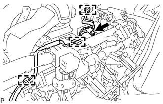
Disconnect the center airbag sensor connector from the center airbag sensor assembly as shown in the illustration.
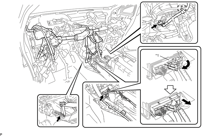
Text in Illustration *1 Center Airbag Sensor Connector - - -
Disengage the 2 clamps.
-
Disconnect each connector.
-
Remove the 9 bolts and instrument panel reinforcement assembly.
-
-
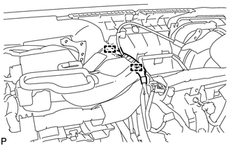
REMOVE AIR CONDITIONING UNIT ASSEMBLY
Note
-
Be sure to support the air conditioning unit assembly when removing it because failure to do so may cause brackets of the air conditioning unit assembly to break.
-
When disassembling the air conditioning unit, eliminate static electricity by touching the vehicle body to prevent the components from being damaged.
-
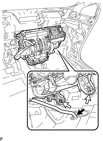
Disconnect the No. 1 cooler unit drain hose.
-
Remove the bolt, nut and air conditioning unit assembly.
-