SFI SYSTEM, Diagnostic DTC:P0704
| DTC Code | DTC Name |
|---|---|
| P0704 | Clutch Switch Input Circuit Malfunction |
DESCRIPTION
The clutch switch assembly is mounted on the clutch pedal. The switch is turned off when depressing the clutch pedal, and transmits a signal to the ECM.
DTC No. |
Detection Item |
DTC Detection Condition |
Trouble Area |
MIL |
Memory |
|---|---|---|---|---|---|
P0704 |
Clutch Switch Input Circuit Malfunction |
No clutch switch signals to ECM despite gears being shifted (3 trip detection logic). |
|
Does not come on |
DTC stored (for M/T models) - (for MMT models) |
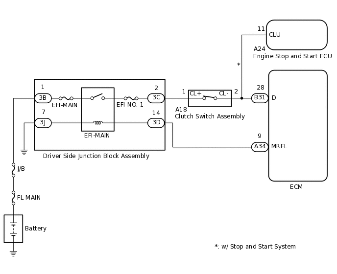
WIRING DIAGRAM
CONFIRMATION DRIVING PATTERN
DTC P0704 is detected when the gears are shifted more than 20 times.
CAUTION / NOTICE / HINT
After replacing the ECM, perform idle learning.
Inspect the fuses for circuits related to this system before performing the following procedure.
PROCEDURE
CHECK CLUTCH SWITCH ASSEMBLY INSTALLATION
Check the clutch switch assembly installation condition.
OK
Clutch switch assembly is installed correctly.
Result
Proceed to
OK
NG
INSPECT CLUTCH SWITCH ASSEMBLY
Inspect the clutch switch assembly.
Result
Proceed to
OK
NG
CHECK TERMINAL VOLTAGE (POWER SOURCE OF CLUTCH SWITCH ASSEMBLY)
Disconnect the clutch switch assembly connector.
Turn the ignition switch to ON.
Measure the voltage according to the value(s) in the table below.
Standard Voltage
Tester Connection
Condition
Specified Condition
A18-1 (CL+) - Body ground
Ignition switch ON
11 to 14 V
Result
Proceed to
OK
NG
NG CHECK HARNESS AND CONNECTOR (CLUTCH SWITCH ASSEMBLY - EFI-MAIN RELAY)Click here
CHECK HARNESS AND CONNECTOR (ECM - CLUTCH SWITCH ASSEMBLY)
Disconnect the ECM connector.
Disconnect the clutch switch assembly connector.
Disconnect the A24 engine stop and start ECU connector. (w/ stop and start system)
Measure the resistance according to the value(s) in the table below.
Standard Resistance
Tester Connection
Condition
Specified Condition
B31-28 (D) - A18-2 (CL-)
Always
Below 1 Ω
B31-28 (D) or A18-2 (CL-) - Body ground
Always
10 kΩ or higher
Result
Proceed to
OK
NG
NG REPAIR OR REPLACE HARNESS OR CONNECTOR
CHECK HARNESS AND CONNECTOR (CLUTCH SWITCH ASSEMBLY - EFI-MAIN RELAY)
Disconnect the clutch switch assembly connector.
Disconnect the driver side junction block assembly connector.
Measure the resistance according to the value(s) in the table below.
Standard Resistance
Tester Connection
Condition
Specified Condition
A18-1 (CL+) - 3C-2
Always
Below 1 Ω
A18-1 (CL+) or 3C-2 - Body ground
Always
10 kΩ or higher
Result
Proceed to
OK
NG
NG REPAIR OR REPLACE HARNESS OR CONNECTOR