BRAKE PEDAL(for RHD with Vacuum Brake Booster) INSTALLATION
PROCEDURE
-
INSTALL BRAKE PEDAL PAD
-
Install the brake pedal pad to the brake pedal support assembly.
Tech Tips
Installation is easier after applying a small amount of soapy water.
-
-
INSTALL BRAKE PEDAL SUPPORT ASSEMBLY
-
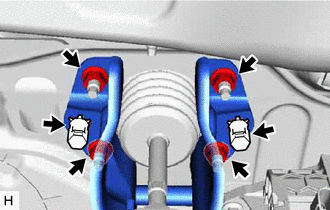
Install the brake pedal support assembly with the 4 nuts.
- Torque:
- 12.7 N*m { 130 kgf*cm, 9 ft.*lbf }
-
Install the 2 clips to the brake pedal support assembly.
-
-
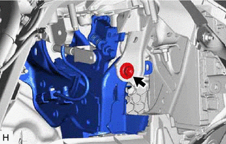
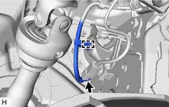
INSTALL PUSH ROD PIN
-
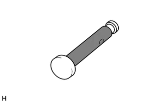

Lithium Soap Base Glycol Grease Apply lithium soap base glycol grease to the push rod pin.
-
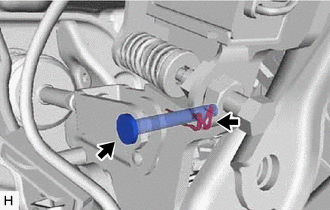
Connect the brake master cylinder push rod clevis to the brake pedal support assembly with the push rod pin, and install a new clip as shown in the illustration.
Note
Be sure to install the push rod pin in the correct direction.
-
-
INSTALL STOP LIGHT SWITCH MOUNTING ADJUSTER
-
INSTALL STOP LIGHT SWITCH ASSEMBLY
-
INSTALL BRAKE PEDAL RETURN SPRING
-
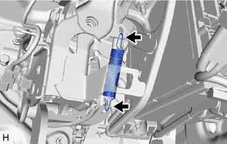
Install the brake pedal return spring to the brake pedal support assembly.
-
-
INSTALL INSTRUMENT PANEL REINFORCEMENT ASSEMBLY
Tech Tips
After performing brake pedal height checks and adjustments, install the instrument panel safety pad sub-assembly.
-
CONNECT BRAKE PEDAL SUPPORT ASSEMBLY
-
Connect the brake pedal support assembly to the instrument panel reinforcement assembly with the bolt.
- Torque:
- 15 N*m { 153 kgf*cm, 11 ft.*lbf }
-
Connect the wire harness clamp to the brake pedal support assembly.
-
Connect the brake pedal load sensing switch connector.
-
-
INSPECT AND ADJUST BRAKE PEDAL
-
INSTALL STEERING COLUMN ASSEMBLY
-
INSTALL INSTRUMENT PANEL SAFETY PAD SUB-ASSEMBLY
-
INSPECT BRAKE PEDAL