EGR COOLER INSTALLATION
PROCEDURE
-
INSTALL NO. 1 EGR COOLER
-
Install a new gasket and the No. 1 EGR cooler to the No. 2 EGR valve assembly with electric EGR control valve assembly with the 4 bolts.
- Torque:
- 25 N*m { 255 kgf*cm, 18 ft.*lbf }
-
-
INSTALL NO. 1 EGR COOLER AND NO. 2 EGR VALVE ASSEMBLY WITH ELECTRIC EGR CONTROL VALVE ASSEMBLY
-
Temporarily install the No. 1 EGR cooler and No. 2 EGR valve assembly with electric EGR control valve assembly to the intake manifold with the 4 bolts.
-
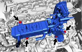
Tighten the 4 bolts in the order shown in the illustration.
Note
Make sure to tighten the bolts in the order.
- Torque:
- 21 N*m { 214 kgf*cm, 15 ft.*lbf }
-
-
INSTALL VACUUM CONTROL VALVE SET
-
INSTALL NO. 1 EGR PIPE SUB-ASSEMBLY (w/o DPF)
-
INSTALL EGR PIPE WITH COOLER SUB-ASSEMBLY (w/ DPF)
-
CONNECT NO. 4 WATER BY-PASS PIPE SUB-ASSEMBLY
-
INSTALL NO. 3 WATER BY-PASS PIPE SUB-ASSEMBLY
-
Install the No. 3 water by-pass pipe sub-assembly to the No. 1 EGR cooler with the 2 bolts.
- Torque:
- 10 N*m { 102 kgf*cm, 7 ft.*lbf }
-
Connect the No. 9 water by-pass hose to the electric EGR control valve assembly, and slide the clamp to secure the hose.
-
Connect the No. 8 water by-pass hose to the No. 3 water by-pass pipe sub-assembly, and slide the clamp to secure the hose.
-
Connect the No. 4 fuel hose to the No. 3 water by-pass pipe sub-assembly.
-
-
INSTALL NO. 2 EGR PIPE
-
INSTALL EGR VALVE BRACKET
-
CONNECT ENGINE WIRE
-
INSTALL NO. 1 UREA TANK FILLER PIPE SUPPORT (w/ Urea SCR System)
-
CONNECT UREA TANK FILLER PIPE ASSEMBLY (w/ Urea SCR System)
-
CONNECT FUEL FILTER ASSEMBLY
-
INSTALL NO. 2 ENGINE COVER BRACKET
-
INSTALL NO. 2 HOSE TO HOSE TUBE
-
INSTALL TURBO PRESSURE SENSOR
-
INSTALL GAS FILTER
-
INSTALL NO. 2 WATER BY-PASS PIPE
-
INSTALL DIESEL THROTTLE BODY ASSEMBLY
-
ADD ENGINE COOLANT
-
INSPECT FOR COOLANT LEAK