METER / GAUGE SYSTEM, Diagnostic DTC:B150718
| DTC Code | DTC Name |
|---|---|
| B150718 | Turn Signal Light Circuit Current Below Threshold |
DESCRIPTION
When the operation signal of the turn signal switch (headlight dimmer switch assembly) is input, the combination meter assembly operates the turn signal lights on the RH and LH sides in response to switch operation. If there is an open in the front or rear turn signal light circuit, the combination meter assembly outputs B150718.
Tech Tips
If there is an open in a front turn signal light circuit or rear turn signal light circuit, the turn signal lights on the side with the open circuit will blink faster than usual.
| DTC No. | Detection Item | DTC Detection Condition | Trouble Area | Memory | Note |
|---|---|---|---|---|---|
| B150718 | Turn Signal Light Circuit Current Below Threshold |
Diagnosis Condition:
Malfunction Status: |
|
DTC stored | - |
WIRING DIAGRAM
Figure 1. for Front Side:
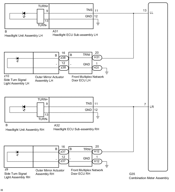
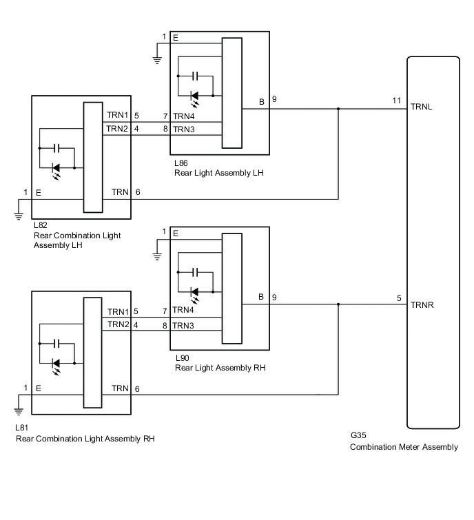
Figure 2. for Rear Side:
CAUTION / NOTICE / HINT
Note
-
Inspect the LEDs for this system before performing the following procedure.
-
When replacing the combination meter assembly, always replace it with a new one. If a combination meter assembly which was installed to another vehicle is used, the information stored in it will not match the information from the vehicle and a DTC may be stored.
PROCEDURE
-
INSPECT LIGHTS
-
Inspect the illumination of each turn signal light.
Result Result Proceed to RH side turn signal light or LH side turn signal light does not illuminate. A Front turn signal light LH does not blink. B Side turn signal light LH does not blink. Front turn signal light RH does not blink. C Side turn signal light RH does not blink. Rear turn signal light LH does not blink. D Rear turn signal light RH does not blink. E
A 
REPLACE COMBINATION METER ASSEMBLY Click here
C 
CHECK TURN SIGNAL LIGHTS (LH SIDE) Click here
D
CHECK HARNESS AND CONNECTOR (REAR LIGHT LH - COMBINATION METER ASSEMBLY OR BODY GROUND) Click here
E
CHECK HARNESS AND CONNECTOR (REAR LIGHT RH - COMBINATION METER ASSEMBLY OR BODY GROUND) Click here
B 
-
-
CHECK TURN SIGNAL LIGHTS (LH SIDE)
-
Turn the engine switch on (IG).
-
Set the turn signal switch to the left turn switch position.
-
Check the operation of the turn signal lights (LH side).
Result Result Proceed to Front turn signal light (LH side) does not blink. A Side turn signal light (LH side) does not blink. B Front turn signal light (LH side) and side turn signal light (LH side) does not blink. C
B
CHECK HARNESS AND CONNECTOR (FRONT MULTIPLEX NETWORK DOOR ECU LH - COMBINATION METER ASSEMBLY OR BODY GROUND) Click here
C
CHECK HARNESS AND CONNECTOR (HEADLIGHT ECU SUB-ASSEMBLY LH - COMBINATION METER ASSEMBLY OR BODY GROUND) Click here
A
-
-
CHECK HARNESS AND CONNECTOR (HEADLIGHT ECU SUB-ASSEMBLY LH - COMBINATION METER ASSEMBLY OR BODY GROUND)
-
Disconnect the A31 headlight ECU sub-assembly LH connector.
-
Disconnect the G35 combination meter assembly connector.
-
Measure the resistance according to the value(s) in the table below.
Standard Resistance (Check for Open) Tester Connection Condition Specified Condition A31-11 (TNS) - G35-13 (LL) Always Below 1 Ω A31-12 (GND) - Body ground Always Below 1 Ω Result Proceed to OK NG
NG
REPAIR OR REPLACE HARNESS OR CONNECTOR
OK
-
-
CHECK HEADLIGHT ECU SUB-ASSEMBLY LH
-
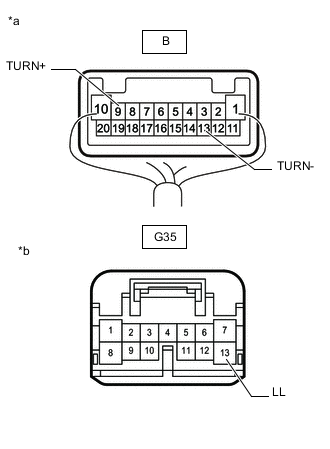
*a Component with harness connected
(Headlight ECU Sub-assembly LH)
*b Front view of wire harness connector
(to Combination Meter Assembly)
Remove the headlight ECU sub-assembly LH as a unit with the connectors still connected.
-
Disconnect the G35 combination meter assembly connector.
-
Measure the resistance according to the value(s) in the table below.
Standard Resistance Tester Connection Condition Specified Condition B-9 (TURN+) - G35-13 (LL) Always Below 1 Ω B-13 (TURN-) - Body ground Always Below 1 Ω Result Proceed to OK NG
OK
REPLACE HEADLIGHT UNIT ASSEMBLY LH Click here
NG
REPLACE HEADLIGHT ECU SUB-ASSEMBLY LH Click here
-
-
CHECK HARNESS AND CONNECTOR (FRONT MULTIPLEX NETWORK DOOR ECU LH - COMBINATION METER ASSEMBLY OR BODY GROUND)
-
Disconnect the H31 front multiplex network door ECU LH connector.
-
Disconnect the G35 combination meter assembly connector.
-
Measure the resistance according to the value(s) in the table below.
Standard Resistance (Check for Open) Tester Connection Condition Specified Condition H31-20 (TRNI) - G35-13 (LL) Always Below 1 Ω H31-1 (GND) - Body ground Always Below 1 Ω Result Proceed to OK NG
NG
REPAIR OR REPLACE HARNESS OR CONNECTOR
OK
-
-
INSPECT OUTER MIRROR ACTUATOR ASSEMBLY LH
-
Remove the outer mirror actuator assembly LH.
-
Inspect the outer mirror actuator assembly LH.
Result Proceed to OK NG
OK
REPLACE FRONT MULTIPLEX NETWORK DOOR ECU LH Click here
NG
-
-
INSPECT SIDE TURN SIGNAL LIGHT ASSEMBLY LH
-
Remove the side turn signal light assembly LH.
-
Inspect the side turn signal light assembly LH.
Result Proceed to OK NG
OK
REPLACE OUTER MIRROR ACTUATOR ASSEMBLY LH Click here
NG
REPLACE SIDE TURN SIGNAL LIGHT ASSEMBLY LH Click here
-
-
CHECK HARNESS AND CONNECTOR (HEADLIGHT ECU SUB-ASSEMBLY LH - COMBINATION METER ASSEMBLY OR BODY GROUND)
-
Disconnect the A31 headlight ECU sub-assembly LH connector.
-
Disconnect the G35 combination meter assembly connector.
-
Measure the resistance according to the value(s) in the table below.
Standard Resistance (Check for Open) Tester Connection Condition Specified Condition A31-11 (TNS) - G35-13 (LL) Always Below 1 Ω Result Proceed to OK NG
OK
REPLACE COMBINATION METER ASSEMBLY Click here
NG
REPAIR OR REPLACE HARNESS OR CONNECTOR
-
-
CHECK TURN SIGNAL LIGHTS (LH SIDE)
-
Turn the engine switch on (IG).
-
Set the turn signal switch to the left turn switch position.
-
Check the operation of the turn signal lights (LH side).
Result Result Proceed to Front turn signal light (LH side) does not blink. A Side turn signal light (LH side) does not blink. B Front turn signal light (LH side) and side turn signal light (LH side) does not blink. C
B
CHECK HARNESS AND CONNECTOR (FRONT MULTIPLEX NETWORK DOOR ECU RH - COMBINATION METER ASSEMBLY OR BODY GROUND) Click here
C
CHECK HARNESS AND CONNECTOR (HEADLIGHT ECU SUB-ASSEMBLY RH - COMBINATION METER ASSEMBLY OR BODY GROUND) Click here
A
-
-
CHECK HARNESS AND CONNECTOR (HEADLIGHT ECU SUB-ASSEMBLY RH - COMBINATION METER ASSEMBLY OR BODY GROUND)
-
Disconnect the A32 headlight ECU sub-assembly RH connector.
-
Disconnect the G35 combination meter assembly connector.
-
Measure the resistance according to the value(s) in the table below.
Standard Resistance (Check for Open) Tester Connection Condition Specified Condition A32-11 (TNS) - G35-7 (LR) Always Below 1 Ω A32-12 (GND) - Body ground Always Below 1 Ω Result Proceed to OK NG
NG
REPAIR OR REPLACE HARNESS OR CONNECTOR
OK
-
-
CHECK HEADLIGHT ECU SUB-ASSEMBLY RH
-
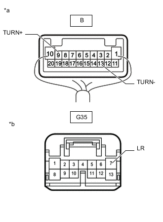
*a Component with harness connected
(Headlight ECU Sub-assembly RH)
*b Front view of wire harness connector
(to Combination Meter Assembly)
Remove the headlight ECU sub-assembly RH as a unit with the connectors still connected.
-
Disconnect the G35 combination meter assembly connector.
-
Measure the resistance according to the value(s) in the table below.
Standard Resistance Tester Connection Condition Specified Condition B-9 (TURN+) - G35-7 (LR) Always Below 1 Ω B-13 (TURN-) - Body ground Always Below 1 Ω Result Proceed to OK NG
OK
REPLACE HEADLIGHT UNIT ASSEMBLY RH Click here
NG
REPLACE HEADLIGHT ECU SUB-ASSEMBLY RH Click here
-
-
CHECK HARNESS AND CONNECTOR (FRONT MULTIPLEX NETWORK DOOR ECU RH - COMBINATION METER ASSEMBLY OR BODY GROUND)
-
Disconnect the H12 front multiplex network door ECU RH connector.
-
Disconnect the G35 combination meter assembly connector.
-
Measure the resistance according to the value(s) in the table below.
Standard Resistance (Check for Open) Tester Connection Condition Specified Condition H12-20 (TRNI) - G35-7 (LR) Always Below 1 Ω H12-1 (GND) - Body ground Always Below 1 Ω Result Proceed to OK NG
NG
REPAIR OR REPLACE HARNESS OR CONNECTOR
OK
-
-
INSPECT OUTER MIRROR ACTUATOR ASSEMBLY RH
-
Remove the outer mirror actuator assembly RH.
-
Inspect the outer mirror actuator assembly RH.
Result Proceed to OK NG
OK
REPLACE FRONT MULTIPLEX NETWORK DOOR ECU RH Click here
NG
-
-
INSPECT SIDE TURN SIGNAL LIGHT ASSEMBLY RH
-
Remove the side turn signal light assembly RH.
-
Inspect the side turn signal light assembly RH.
Result Proceed to OK NG
OK
REPLACE OUTER MIRROR ACTUATOR ASSEMBLY RH Click here
NG
REPLACE SIDE TURN SIGNAL LIGHT ASSEMBLY RH Click here
-
-
CHECK HARNESS AND CONNECTOR (HEADLIGHT ECU SUB-ASSEMBLY RH - COMBINATION METER ASSEMBLY OR BODY GROUND)
-
Disconnect the A32 headlight ECU sub-assembly RH connector.
-
Disconnect the G35 combination meter assembly connector.
-
Measure the resistance according to the value(s) in the table below.
Standard Resistance (Check for Open) Tester Connection Condition Specified Condition A32-11 (TNS) - G35-7 (LR) Always Below 1 Ω Result Proceed to OK NG
OK
REPLACE COMBINATION METER ASSEMBLY Click here
NG
REPAIR OR REPLACE HARNESS OR CONNECTOR
-
-
CHECK HARNESS AND CONNECTOR (REAR LIGHT LH - COMBINATION METER ASSEMBLY OR BODY GROUND)
-
Disconnect the L86 rear light assembly LH connector.
-
Disconnect the L82 rear combination light assembly LH connector.
-
Disconnect the G35 combination meter assembly connector.
-
Measure the resistance according to the value(s) in the table below.
Standard Resistance (Check for Open) Tester Connection Condition Specified Condition L86-9 (B) - G35-11 (TRNL) Always Below 1 Ω L82-6 (TRN) - G35-11 (TRNL) Always Below 1 Ω L86-1 (E) - Body ground Always Below 1 Ω L82-1 (E) - Body ground Always Below 1 Ω Result Proceed to OK NG
NG
REPAIR OR REPLACE HARNESS OR CONNECTOR
OK
-
-
CHECK HARNESS AND CONNECTOR (REAR COMBINATION LIGHT ASSEMBLY LH - REAR LIGHT ASSEMBLY LH)
-
Disconnect the L86 rear light assembly LH connector.
-
Disconnect the L82 rear combination light assembly LH connector.
-
Measure the resistance according to the value(s) in the table below.
Standard Resistance (Check for Open) Tester Connection Condition Specified Condition L82-5 (TRN1) - L86-7 (TRN4) Always Below 1 Ω L82-4 (TRN2) - L86-8 (TRN3) Always Below 1 Ω Result Proceed to OK NG
NG
REPAIR OR REPLACE HARNESS OR CONNECTOR
OK
-
-
INSPECT REAR COMBINATION LIGHT LENS AND BODY LH
-
Remove the rear combination lens and body LH.
-
Inspect the rear combination lens and body LH.
Result Proceed to OK NG
NG
REPLACE REAR COMBINATION LIGHT LENS AND BODY LH Click here
OK
-
-
INSPECT REAR LIGHT LENS AND BODY LH
-
Remove the rear lens and body LH.
-
Inspect the rear lens and body LH.
Result Proceed to OK NG
OK
REPLACE COMBINATION METER ASSEMBLY Click here
NG
REPLACE REAR LIGHT LENS AND BODY LH Click here
-
-
CHECK HARNESS AND CONNECTOR (REAR LIGHT RH - COMBINATION METER ASSEMBLY OR BODY GROUND)
-
Disconnect the L90 rear light assembly RH connector.
-
Disconnect the L81 rear combination light assembly RH connector.
-
Disconnect the G35 combination meter assembly connector.
-
Measure the resistance according to the value(s) in the table below.
Standard Resistance (Check for Open) Tester Connection Condition Specified Condition L90-9 (B) - G35-5 (TRNR) Always Below 1 Ω L81-6 (TRN) - G35-5 (TRNR) Always Below 1 Ω L90-1 (E) - Body ground Always Below 1 Ω L81-1 (E) - Body ground Always Below 1 Ω Result Proceed to OK NG
NG
REPAIR OR REPLACE HARNESS OR CONNECTOR
OK
-
-
CHECK HARNESS AND CONNECTOR (REAR COMBINATION LIGHT ASSEMBLY RH - REAR LIGHT ASSEMBLY RH)
-
Disconnect the L90 rear light assembly RH connector.
-
Disconnect the L81 rear combination light assembly RH connector.
-
Measure the resistance according to the value(s) in the table below.
Standard Resistance (Check for Open) Tester Connection Condition Specified Condition L81-5 (TRN1) - L90-7 (TRN4) Always Below 1 Ω L81-4 (TRN2) - L90-8 (TRN3) Always Below 1 Ω Result Proceed to OK NG
NG
REPAIR OR REPLACE HARNESS OR CONNECTOR
OK
-
-
INSPECT REAR COMBINATION LIGHT LENS AND BODY RH
-
Remove the rear combination lens and body RH.
-
Inspect the rear combination lens and body RH.
Result Proceed to OK NG
NG
REPLACE REAR COMBINATION LIGHT LENS AND BODY RH Click here
OK
-
-
INSPECT REAR LIGHT LENS AND BODY RH
-
Remove the rear lens and body RH.
-
Inspect the rear lens and body RH.
Result Proceed to OK NG
OK
REPLACE COMBINATION METER ASSEMBLY Click here
NG
REPLACE REAR LIGHT LENS AND BODY RH Click here
-