SOLAR SENSOR INSPECTION
PROCEDURE
INSPECT AUTOMATIC LIGHT CONTROL SENSOR (SOLAR SENSOR)
-
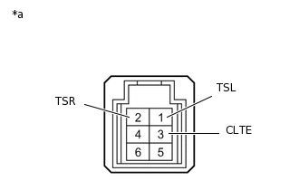
*a
Component without wire harness connected
(Automatic Light Control Sensor (Solar Sensor))
Connect the battery's positive (+) lead of the auxiliary battery to terminal 6 and the negative (-) lead to terminal 3, and then measure the voltage according to the value(s) in the table below.
Standard Voltage
Tester Connection
Condition
Specified Condition
1 (TSL) - 3 (CLTE)
Sensor subjected to electric light
4.0 to 4.6 V
1 (TSL) - 3 (CLTE)
Sensor covered with a cloth
0.8 V or less
2 (TSR) - 3 (CLTE)
Sensor subjected to electric light
4.0 to 4.6 V
2 (TSR) - 3 (CLTE)
Sensor covered with a cloth
0.8 V or less
Note:The connection procedure for using a digital tester such as a TOYOTA electrical tester is shown above.
Tip:As the inspection light is moved away from the sensor, the voltage increases.
Use an incandescent light for inspection. Bring it within 30 cm (11.8 in.) of the automatic light control sensor (solar sensor).
If the result is not as specified, replace the automatic light control sensor (solar sensor).
-