HYBRID CONTROL SYSTEM
-
FUNCTION OF MAIN COMPONENTS
-
The main components of the hybrid system have the following functions:
Component Function Hybrid Vehicle Control ECU Assembly
-
Performs comprehensive control of the hybrid system.
-
Information from various sensors as well as from ECUs (ECM, MG ECU, battery voltage sensor and skid control ECU assembly) is received, and based on this the required torque and output power is calculated. The hybrid vehicle control ECU assembly transmits the calculated result to the ECM, MG ECU and skid control ECU assembly.
-
Monitors the SOC of the HV battery.
-
Controls the DC-DC converter.
-
Controls the inverter water pump assembly.
-
Controls the battery cooling blower assembly.
2AR-FSE Engine The 2AR-FSE engine is a high-expansion ratio Atkinson cycle engine which is compatible with the hybrid system and which generates drive force for driving and energy for electricity generation. L210 Hybrid Vehicle Transmission Assembly Generator (MG1) Generator (MG1), which is driven by the engine, generates high-voltage electricity in order to operate motor (MG2) and charge the HV battery. Also, it functions as a starter to start the engine. Motor (MG2)
-
Motor (MG2), which is driven by electrical power from generator (MG1) and the HV battery, generates motive force for the drive wheels.
-
During braking, or when the accelerator pedal is not depressed, it generates high-voltage electricity to recharge the HV battery.
Generator Resolver Detects the rotor position, rotational speed and direction of generator (MG1). Motor Resolver Detects the rotor position, rotational speed and direction of motor (MG2). Generator Temperature Sensor Detects the temperature of generator (MG1). Motor Temperature Sensor Detects the temperature of motor (MG2). Compound Gear Unit Power Split Planetary Gear Unit Distributes the engine motive force as appropriate to directly drive the vehicle as well as generator (MG1). Motor Speed Reduction Planetary Gear Unit Reduces the rotational speed of motor (MG2) in accordance with the characteristics of the planetary gear, in order to increase torque. Inverter with Converter Assembly Inverter Converts the direct current from the boost converter into alternating current for generator (MG1) and motor (MG2), and vice versa (from AC to DC). Boost Converter Boosts the HV battery nominal voltage of DC 230.4 V up to a maximum voltage of DC 650 V and vice versa (steps down DC 650 V to DC 230.4 V). DC-DC Converter Steps down the HV battery nominal voltage of DC 230.4 V to approximately DC 14 V in order to supply electricity to the electrical components, as well as to recharge the auxiliary battery. MG ECU Controls the inverter and boost converter in accordance with the signals received from the hybrid vehicle control ECU assembly , thus operating generator (MG1) and motor (MG2) as either a generator or motor. Atmospheric Pressure Sensor Detects the atmospheric pressure. Temperature Sensor for Inverter with Converter Assembly Detects temperatures in the parts of the inverter with converter assembly as well as the HV coolant temperature. Inverter Current Sensor Detects the current of generator (MG1) and motor (MG2). HV Battery Assembly HV Battery (Battery Modules)
-
Supplies electrical power to generator (MG1) and motor (MG2) in accordance with the driving conditions of the vehicle.
-
Recharged by generator (MG1) and motor (MG2) in accordance with the SOC and the driving conditions of the vehicle.
HV Battery Temperature Sensor Detects temperatures in the parts of the HV battery. HV Battery Intake Air Temperature Sensor Detects the intake air temperature from the battery cooling blower assembly. Hybrid Battery Junction Block Assembly System Main Relays Connects and disconnects the high-voltage circuit between the HV battery and the inverter with converter assembly through the use of signals from the hybrid vehicle control ECU assembly. HV Battery Current Sensor Detects the input and output current of the HV battery. Battery Voltage Sensor
-
Monitors the conditions of the HV battery such as voltage, current and temperature, and transmits this information to the hybrid vehicle control ECU assembly.
-
Monitors the high-voltage system for breakdown of the electrical insulation.
Service Plug Grip Shuts off the high-voltage circuit of the HV battery when the service plug grip is removed for vehicle inspection or maintenance. Interlock Switch (for Service Plug Grip/for Inverter Terminal Cover/for Connector Cover Assembly/for Power Cable Connector) Verifies that the service plug grip, inverter terminal cover, connector cover assembly and inverter power cable connector are installed. Power Cable (Frame Wire) Connects the HV battery, inverter with converter assembly, hybrid vehicle transmission assembly and compressor with motor assembly. Inverter Water Pump Assembly Controlled in 4 stages by the hybrid vehicle control ECU assembly in accordance with inverter coolant temperatures in order to cool the inverter coolant. Battery Cooling Blower Assembly Operates under the control of the hybrid vehicle control ECU assembly in order to cool the HV battery. Auxiliary Battery Supplies electricity to the electrical components. Auxiliary Battery Temperature Sensor (Thermistor Assembly) Detects the temperature of the auxiliary battery. Power Switch Starts and stops the hybrid system. Accelerator Pedal Sensor Assembly Converts the accelerator pedal position into an electrical signal and sends it to the hybrid vehicle control ECU assembly. Kick Down Switch Assembly Detects that the accelerator pedal is almost fully depressed. Cruise Control Main Switch*1 Turns the cruise control system and dynamic radar cruise control system on and off, and conducts various operations including vehicle speed setting, acceleration, deceleration and control cancellation. Shift Paddle Switch (Transmission Shift Switch Assembly) Detects the driver's shift-up and shift-down operations. Transmission Control Switch (Transmission Floor Shift Assembly)
-
Detects that the shift lever is in S.
-
Detects the driver's shift-up and shift-down operations when the shift lever is in S.
Shift Lever Position Sensor Converts the shift position into electrical signals and sends them to the hybrid vehicle control ECU assembly. Stop Light Switch Assembly Detects the depression of the brake pedal. Combination Switch Assembly EV Drive Mode Switch Sends the EV drive mode switch signal to the hybrid vehicle control ECU assembly when operated by the driver. Drive Mode Select
-
Outputs the NORMAL mode signal to the hybrid vehicle control ECU assembly via the ECM when operated by the driver.
-
Outputs the ECO mode signal to the hybrid vehicle control ECU assembly via the air conditioning amplifier assembly when operated by the driver.
-
Outputs the SPORT*2 or SPORT S/S+*3 mode signal to the hybrid vehicle control ECU assembly via the ECM when operated by the driver.
SNOW Mode Switch Outputs the SNOW mode switch signal to the hybrid vehicle control ECU assembly via the ECM when operated by the driver. ECM
-
Performs control of the engine in accordance with the target engine speed and required engine motive force received from the hybrid vehicle control ECU assembly.
-
Transmits various engine operating condition signals to the hybrid vehicle control ECU assembly.
Skid Control ECU Assembly
-
During braking, it calculates the required regenerative braking force and transmits it to the hybrid vehicle control ECU assembly.
-
Transmits the request to the hybrid vehicle control ECU assembly to limit motive force while the TRC or VSC is operating.
Air Conditioning Amplifier Assembly Transmits various air conditioning state signals to the hybrid vehicle control ECU assembly. Airbag Sensor Assembly During a collision, it transmits the airbag deployment signal to the hybrid vehicle control ECU assembly. Driving Support ECU Assembly*4 Sends the information about the operation conditions of the dynamic radar cruise control system to the hybrid vehicle control ECU assembly. Radio Receiver Assembly
-
Displays hybrid system output and charging of the hybrid battery on the energy monitor in the multi-display.
-
Displays drive mode on the multi-display.
Combination Meter Assembly Hybrid System Indicator Displays the system power output and regenerative charging of the hybrid system. When SPORT*2, SPORT S*3 or SPORT S+*3 mode is selected, the tachometer replaces the hybrid system indicator. READY Indicator Light Informs the driver that the vehicle is ready to drive. Master Warning Light Illuminates or flashes and the buzzer may sound depending on the message displayed on the multi-information display. EV Drive Indicator Light Turns on during EV driving. Charge Warning Light Turns on when there is a malfunction in the auxiliary battery charging system. Malfunction Indicator Lamp (MIL) Turns on when there is a malfunction in the hybrid control system and engine control system. Multi-information Display
-
Displays the shift lever position.
-
Displays the shift range.
-
Displays the energy flow.
-
Displays the EV mode.
-
Displays the drive mode.
-
Displays the SNOW mode.
-
Displays messages to inform the driver when a malfunction occurs.
-
Shows system status and appropriate operations to be performed.
*1: Models with cruise control system or dynamic radar cruise control system
*2: Models without adaptive variable suspension system
*3: Models with adaptive variable suspension system
*4: Models with dynamic radar cruise control system
-
-
-
SYSTEM CONTROL
-
Control List
-
The hybrid system consists of the controls listed below.
Control Outline Hybrid Vehicle Control
-
The hybrid vehicle control ECU assembly calculates the target motive force based on the shift lever position sensor, the degree to which the accelerator pedal is depressed, and the vehicle speed. It performs control in order to create the target motive force by optimally combining generator (MG1), motor (MG2) and the engine.
-
The hybrid vehicle control ECU assembly calculates the engine motive force based on the target motive force, which has been calculated based on the requirements of the driver and the driving conditions of the vehicle. In order to create this motive force, the hybrid vehicle control ECU assembly transmits the signals to the ECM.
-
The hybrid vehicle control ECU assembly monitors the SOC of the HV battery and the temperature of the HV battery, generator (MG1) and motor (MG2), in order to optimally control these items.
SOC Control
-
The hybrid vehicle control ECU assembly calculates the SOC by estimating the charging and discharging amperage of the HV battery.
-
The hybrid vehicle control ECU assembly constantly performs charge/discharge control based on the calculated SOC in order to maintain the SOC within its target range.
Engine Control The ECM receives the target engine speed and required engine motive force, which were sent from the hybrid vehicle control ECU assembly, and controls the ETCS-i, fuel injection volume, ignition timing, Dual VVT-i and EGR*1. Inverter Control
-
The inverter converts the direct current from the HV battery into alternating current for generator (MG1) and motor (MG2), or vice versa, in accordance with the signals provided by the hybrid vehicle control ECU assembly via the MG ECU. In addition, the inverter is used to transfer power from generator (MG1) to motor (MG2).
-
The hybrid vehicle control ECU assembly shuts down the inverter if it receives an overheating, overcurrent or voltage fault signal from the inverter via the MG ECU.
Boost Converter Control
-
The boost converter boosts the HV battery nominal voltage of DC 230.4 V up to a maximum voltage of DC 650 V, in accordance with the signals provided by the hybrid vehicle control ECU assembly via the MG ECU.
-
The inverter converts the alternating current generated by generator (MG1) or motor (MG2) into the direct current. The boost converter steps down the generated voltage of DC 650 V (maximum voltage) to approximately DC 230.4 V, in accordance with the signals provided by the hybrid vehicle control ECU assembly via the MG ECU.
DC-DC Converter Control The DC-DC converter steps down the HV battery nominal voltage of DC 230.4 V to approximately DC 14 V in order to supply electricity to the electrical components, as well as to recharge the auxiliary battery. System Main Relay Control To ensure that it is possible to connect and disconnect the high-voltage circuits reliably, the hybrid vehicle control ECU assembly controls the 3 system main relays to connect and disconnect the high-voltage circuits from the HV battery. The hybrid vehicle control ECU assembly also uses the timing of the operation of the 3 system main relays to monitor the operation of the relay contacts. Cooling System Control for Inverter with Converter Assembly In order to cool the inverter with converter assembly, generator (MG1) and motor (MG2), the hybrid vehicle control ECU assembly regulates the inverter water pump assembly according to the signals from the temperature sensor for inverter with converter assembly, generator temperature sensor and motor temperature sensor. Cooling System Control for HV Battery In order to maintain the HV battery temperature at the optimum level, the hybrid vehicle control ECU assembly regulates the battery cooling blower assembly according to the signals from the HV battery temperature sensors and HV battery intake air temperature sensor. Regenerative Braking Cooperative Control During braking, the skid control ECU assembly calculates the required regenerative braking force and transmits it to the hybrid vehicle control ECU assembly. Upon receiving this signal, the hybrid vehicle control ECU assembly transmits the actual regenerative braking control value to the skid control ECU assembly. Based on this result, the skid control ECU assembly calculates and executes the required hydraulic braking force. TRC/VSC Cooperative Control The skid control ECU assembly transmits the request to the hybrid vehicle control ECU assembly to limit motive force while the TRC or VSC is operating. The hybrid vehicle control ECU assembly controls the engine and motor (MG2) in accordance with the present driving conditions in order to suppress the motive force. For details, refer to Brake Control System. During Collision Control During a collision, if the hybrid vehicle control ECU assembly receives the airbag deployment signal from the airbag sensor assembly, it turns the system main relays off in order to shut off the high-voltage from the HV battery. Cruise Control System Operation Control*2 When the hybrid vehicle control ECU assembly receives the cruise control switch signal, it controls the motive forces of the engine and motor (MG2) to be an optimum combination in order to obtain the target vehicle speed by the driver's demand. For details, refer to Cruise Control System. Dynamic Radar Cruise Control System Operation Control*3 Upon receiving a motive force request signal from the driving support ECU, the hybrid vehicle control ECU assembly controls the motive forces of the engine and motor (MG2) to be an optimum combination in order to obtain the target vehicle speed. Shift Control The hybrid vehicle control ECU assembly detects the driver's desired shift state (P, R, N, D or S) in accordance with the signals provided by the shift lever position sensor and park/neutral position switch assembly. Based on these inputs and vehicle operating conditions, the hybrid vehicle control ECU assembly generator (MG1), motor (MG2) and the engine to match the selected shift state. EV Drive Mode Control When the EV drive mode switch (combination switch assembly) is operated by the driver, the hybrid vehicle control ECU assembly uses only motor (MG2) to drive the vehicle if the operating conditions are satisfied. Drive Mode Select Control Optimally controls the outputs of generator (MG1), motor (MG2) and engine in accordance with the following drive modes: NORMAL, ECO, SPORT*4 and SPORT S/S+*5 modes. SNOW Mode Control When the SNOW mode switch is manually operated by the driver, the hybrid vehicle control ECU assembly controls motive force for the acceleration operation, thus achieving smooth start-off on slippery roads such as snowy roads. Brake Override System The driving torque is restricted when both the accelerator and brake pedals are depressed. (For the Activation Conditions and Inspection Method, refer to the Repair Manual) Engine Immobiliser Prohibits fuel delivery, ignition and starting the hybrid control system if an attempt is made to start the hybrid control system with an invalid key. *1: Models with EGR system
*2: Models with cruise control system
*3: Models with dynamic radar cruise control system
*4: Models without adaptive variable suspension system
*5: Models with adaptive variable suspension system
-
-
-
Hybrid System Activation (READY-on State)
-
The hybrid system is activated by pressing the power switch while the brake pedal is being depressed. At this time, the READY indicator light flashes until the system check is completed. When the READY indicator light turns on, the hybrid system has started and the vehicle is ready to drive.
-
Even if the driver turns the power switch on (READY), sometimes the hybrid vehicle control ECU assembly will not start the engine. The engine will only start if conditions such as engine coolant temperature, SOC, HV battery temperature and electrical load require an engine start.
-
After driving, when the driver stops the vehicle and moves the shift lever to P, the hybrid vehicle control ECU assembly allows the engine to continue running. The engine will stop after the SOC, HV battery temperature and electrical load reach a specified level.
Note
When the hybrid system is unavoidably required to be stopped while driving, the system can be forced to stop by pressing and holding the power switch for approximately 2 seconds or more or pushing the power switch 3 times or more in a row. At this time, the power source will change to on (ACC). Thereafter, the hybrid system can be restarted by pressing the power switch with the shift lever in N (the system may not restart due to the vehicle conditions).
-
-
EV Drive Mode
-
When all required conditions, some of which are listed below, are satisfied, EV drive mode can be used.
Operating Condition
-
The hybrid system temperature is not high. (The hybrid system temperature will be high when the outside air temperature is high or after the vehicle has traveled up a hill or at high speeds.)
-
The hybrid system temperature is not low. (The hybrid system temperature will be low after the vehicle has been left for a long time when the outside air temperature is low.)
-
The SOC is approximately 50% or higher.
-
The vehicle speed is approximately 30 km/h (19 mph) or less. (Cold Engine Conditions)
-
The vehicle speed is approximately 45 km/h (28 mph) or less. (Warm Engine Conditions)
-
The accelerator pedal depression amount is a certain level or below.
-
The defroster is off.
-
The cruise control system is not operating.*
*: Models with cruise control system or dynamic radar cruise control system
Tech Tips
The available cruising range during EV drive mode varies according to the SOC of the HV battery and the driving conditions such as road surfaces and hills. However, it is usually between several hundred meters (several hundred yards) and approximately 2 km (1.2 miles).
-
-
EV drive mode has been provided to reduce vehicle noise, such as when entering or leaving a garage, as well as reducing the production of exhaust fumes in a garage. When the EV drive mode switch is operated by the driver, the hybrid vehicle control ECU assembly uses only motor (MG2) to drive the vehicle if the operating conditions are satisfied.
-
When all operating conditions are satisfied, pressing the EV drive mode switch causes the vehicle to enter EV drive mode, and the EV mode indicator light and EV drive indicator light will be illuminated. If any operating condition is not satisfied and the EV drive mode switch is pressed, a message is displayed on the multi-information display and a buzzer sounds to inform the driver that the EV drive mode switch operation was rejected, and EV drive mode cannot be entered.
-
If the operating conditions are no longer met while the vehicle is traveling in EV drive mode, in order to inform the driver that EV drive mode will be canceled, a message is displayed on the multi-information display and a buzzer sounds.
-
-
Drive Mode Select Control
-
The drive mode can be selected by operating the drive mode select.
-
The selected drive mode will be shown on the multi-information display in the combination meter assembly.
-
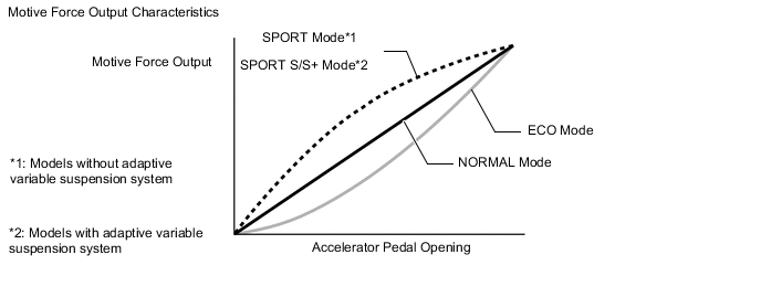
The drive characteristics of each drive mode are as follows:
Drive Mode Outline NORMAL Mode This drive mode provides optimum driveability. ECO Mode The hybrid vehicle control ECU assembly optimizes fuel economy and driving performance by gently generating the motive force in comparison to the accelerator pedal operation. At the same time, the ECU supports eco driving by optimizing the air conditioning performance. SPORT Mode*1
SPORT S Mode*2
The hybrid vehicle control ECU assembly controls motive force in the intermediate area of accelerator pedal opening to a greater degree than that of NORMAL mode, thus improving acceleration performance. In addition, engine speed response performance has been improved in the high area of accelerator pedal opening, thus producing a sporty drive. SPORT S+ Mode*2 In addition to the control when in SPORT S mode, the suspension control system and steering control system have been integrated to shift to SPORT S+ mode, improved operability and stability have been aimed for even without losing comfort and a control which enables operation appropriate to the driver's intention is performed. *1: Models without adaptive variable suspension system
*2: Models with adaptive variable suspension system
-
-
SNOW Mode Control
-
SNOW mode can be selected by operating the SNOW mode switch.
-
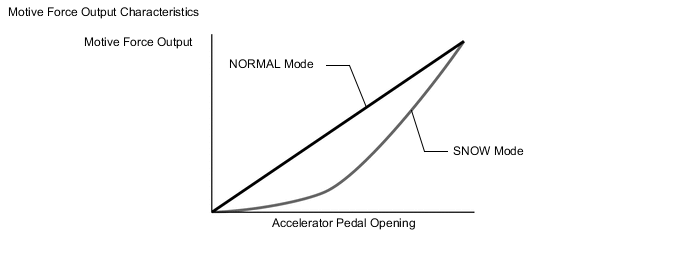
When SNOW mode is selected, the hybrid vehicle control ECU assembly improves starting-off performance and acceleration performance on slippery road surfaces such as snow on which the wheels may spin by controlling the restraint of motive force more than when in NORMAL mode.
-
When SNOW mode control is activated, the motive force that changes in accordance with the accelerator pedal operation is controlled to be smaller than NORMAL mode around the accelerator pedal angle which causes the wheels to slip easily, achieving enhanced accelerator pedal controllability.
-
-
-
DIAGNOSIS
-
When the hybrid vehicle control ECU assembly detects a malfunction in the hybrid system, the hybrid vehicle control ECU assembly performs diagnosis and memorizes information related to the fault. To inform the driver of the malfunction, the hybrid vehicle control ECU assembly illuminates or blinks the Malfunction Indicator Lamp (MIL). At the same time, a Diagnostic Trouble Code (DTC) is stored in memory.
-
3-digit information codes (INF codes) are provided with a conventional DTC as a subset of the primary 5-digit code. This enables the troubleshooting procedure to further narrow down the possible trouble areas to identify the problem.
-
DTCs can be read by connecting the Global TechStream (GTS) to the DLC3. For details, refer to the Repair Manual.
-