ELECTRONIC CONTROLLED AUTOMATIC TRANSMISSION SYSTEM (for 1KD-FTV) A/T P Indicator Circuit
DESCRIPTION
The propeller shaft and wheels are free even when the transmission shift lever is on P, as long as the transfer shift lever is on N. The A/T P indicator illuminates to warn the driver that the propeller shaft and wheels are not locked.
If the A/T P indicator illuminates, the transfer shift lever should be moved from N.
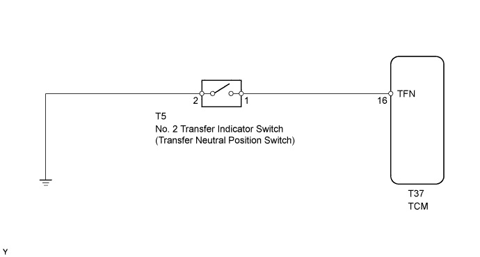
WIRING DIAGRAM
INSPECTION PROCEDURE
PROCEDURE
-
INSPECT PARK/NEUTRAL POSITION SWITCH
-
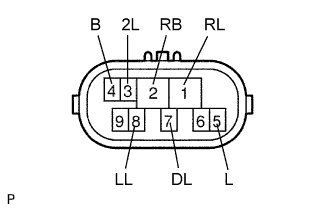
Disconnect the N1 park/neutral position switch connector.
-
Measure the resistance of the park/neutral position switch when the shift lever is moved to each position.
Standard resistance Tester Connection Shift Lever Position Specified Condition 4 (B) - 5 (L) P or N Below 1 Ω 4 (B) - 5 (L) Not on P or N 10 kΩ or higher 1 (RL) - 2 (RB) R Below 1 Ω 1 (RL) - 2 (RB) Not on R 10 kΩ or higher 2 (RB) - 7 (DL) D Below 1 Ω 2 (RB) - 7 (DL) Not on D 10 kΩ or higher 2 (RB) - 3 (2L) 2 Below 1 Ω 2 (RB) - 3 (2L) Not on 2 10 kΩ or higher 2 (RB) - 8 (LL) L Below 1 Ω 2 (RB) - 8 (LL) Not on L 10 kΩ or higher
NG 
REPLACE PARK/NEUTRAL POSITION SWITCH
OK 
-
-
INSPECT NO. 2 TRANSFER INDICATOR SWITCH (TRANSFER NEUTRAL POSITION SWITCH)
-
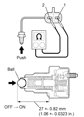
Remove the transfer indicator switch.
-
Measure the resistance of the switch when pushing the ball at the tip of the switch.
Standard resistance Tester Connection Switch Condition Specified Condition 1 - 2 Not pushed 10 kΩ or higher 1 - 2 Pushed Below 1 Ω
NG
REPLACE NO. 2 TRANSFER INDICATOR SWITCH (TRANSFER NEUTRAL POSITION SWITCH)
OK
-
-
INSPECT COMBINATION METER
-
Check the A/T P indicator light.
-
Disconnect the T5 switch connector.
-
Turn the ignition switch ON.
-
Connect the T5-1 terminal of the wire harness side connector to the body ground, and then check the A/T P indicator light.
OK A/T P indicator light illuminates.
-
NG
REPLACE COMBINATION METER
OK 
REPAIR OR REPLACE HARNESS AND CONNECTOR
-