INSTRUMENT PANEL SAFETY PAD REASSEMBLY
CAUTION / NOTICE / HINT
Tech Tips
-
Use the same procedure for LHD and RHD vehicles.
-
The procedure listed below is for the LHD vehicles.
PROCEDURE
-
INSTALL NO. 1 INSTRUMENT PANEL CUSHION
-
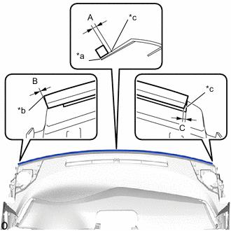
*a Instrument Panel Front Side End *b Instrument Panel Left Side End *c Marking Install a new instrument panel cushion as shown in the illustration.
Standard Measurement Area Measurement A 3.0 mm (0.118 in.) B 0 mm (0 in.) C 2.0 mm (0.0787 in.) Tech Tips
Peel off the backing paper from the double-sided tape before installing the No. 1 instrument panel cushion.
-
-
INSTALL NO. 1 INSTRUMENT PANEL PIN
Tech Tips
Use the same procedure as for the opposite side.
-
Engage the guide to install the No. 1 instrument panel pin.
-
Install the screw <D> or screw <M>.
-
-
INSTALL NO. 2 INSTRUMENT PANEL WIRE
-
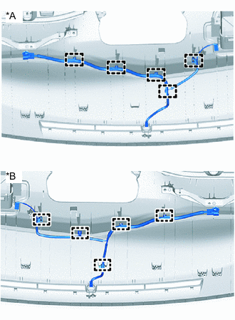
*A for LHD *B for RHD w/ Ion Generator:
-
Engage the clamps to install the No. 2 instrument panel wire.
-
-
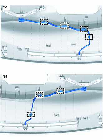
*A for LHD *B for RHD w/o Ion Generator:
-
Engage the clamps to install the No. 2 instrument panel wire.
-
-
-
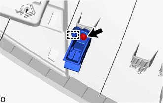
INSTALL AUTOMATIC LIGHT CONTROL SENSOR
-
INSTALL ANTENNA CORD SUB-ASSEMBLY
-
for LHD:
-
for RHD:
-
-
INSTALL ION GENERATOR SUB-ASSEMBLY (w/ Ion Generator)
-
INSTALL INSTRUMENT PANEL PASSENGER AIRBAG ASSEMBLY
-
INSTALL NO. 2 INSTRUMENT PANEL REGISTER ASSEMBLY
-
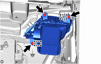
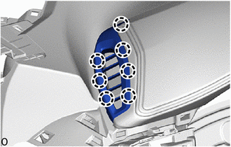
Engage the guides to install the No. 2 instrument panel register assembly.
-
Install the 3 screws <D> or 3 screws <M>.
-
-
INSTALL NO. 1 INSTRUMENT PANEL REGISTER ASSEMBLY
-
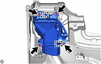
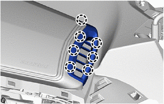
Engage the guides to install the No. 1 instrument panel register assembly.
-
Install the 4 screws <D> or 4 screws <M>.
-
-
INSTALL NO. 3 HEATER TO REGISTER DUCT SUB-ASSEMBLY
-
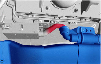
w/ Ion Generator:
-
Connect the rear air duct sub-assembly.
-
-
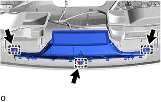
Engage the guides to install the No. 3 heater to register duct sub-assembly.
-
Install the 3 screws <D> or 3 screws <M>.
-
-
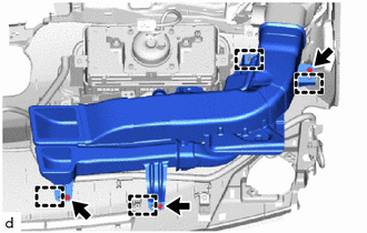
INSTALL NO. 1 HEATER TO REGISTER DUCT SUB-ASSEMBLY
-
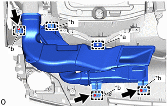
*a Clamp *b Guide Engage the guides to install the No. 1 heater to register duct sub-assembly.
-
Install the 3 screws <D> or 3 screws <M>.
-
Engage the clamp to connect the No. 2 instrument panel wire.
-
-
INSTALL DEFROSTER NOZZLE ASSEMBLY
-
w/ Antenna Divider:
-
Connect the connector.
-
-
Engage the guides to install the defroster nozzle assembly.
-
Install the 3 screws <D> or 3 screws <M>.
-
-
INSTALL NO. 2 SIDE DEFROSTER NOZZLE
-
Engage the claws to install the No. 2 side defroster nozzle.
-
-
INSTALL NO. 1 SIDE DEFROSTER NOZZLE
-
Engage the claws to install the No. 1 side defroster nozzle.
-