HYBRID TRANSAXLE SYSTEM
-
OUTLINE
-
A P313 hybrid vehicle transaxle assembly is used.
-
Containing the motor (MG2) for driving the vehicle and generator (MG1) for generating electrical power, this transaxle uses a continuously variable transmission mechanism with a compound gear unit that achieves smooth and quiet operation.
-
This hybrid vehicle transaxle assembly consists primarily of a generator (MG1), motor (MG2), compound gear unit, transmission input damper assembly, counter gear, final gear, differential gear unit and oil pump.
-
A sequential shiftmatic system is used, enabling a shift range selection operation that feels like a manual transmission vehicle using the shift paddle switch (transmission shift switch assembly)* and shift lever. In addition, even when driving with the shift lever in D, the shift paddle operation (shift range selection operation using the shift paddle) has been made available.*
*: Models with shift paddle switch (transmission shift switch assembly)
-
-
SPECIFICATION
Item Specification Transaxle Type P313 Shift Position P / R / N / D / S Compound Gear Unit Power Split Planetary Gear Unit No. of Sun Gear Teeth 30 No. of Pinion Gear Teeth 23 No. of Ring Gear Teeth 78 Motor Speed Reduction Planetary Gear Unit No. of Sun Gear Teeth 23 No. of Pinion Gear Teeth 18 No. of Ring Gear Teeth 57 Counter Gear No. of Drive Gear Teeth 54 No. of Driven Gear Teeth 55 Final Gear No. of Drive Gear Teeth 25*1
23*2
No. of Driven Gear Teeth 77*1
80*2
Total Speed Reduction Ratio*3 3.137*1
3.542*2
Oil Type TOYOTA Genuine ATF WS Fluid Capacity Liters (US qts, Imp. qts) 4.8 (5.1, 4.2) Weight (Reference)*4 kg (lb) 123 (271.2) *1: Except destination package for South Korea
*2: Destination package for South Korea
*3: The ratio of the combination of the counter and final gears.
*4: The weight shown is with the transaxle fully filled with fluid and transmission input damper assembly.
-
MAIN FEATURES
-
This hybrid vehicle transaxle assembly has a 3-shaft configuration. The compound gear unit, transmission input damper assembly, oil pump, counter drivegear generator, (MG1) and motor (MG2) are provided on the input shaft. The counter driven gear and final drive gear are provided on the 2nd shaft. The final driven gear and differential gear unit are provided on the 3rd shaft.
-
The engine, generator (MG1) and motor (MG2) are mechanically joined via the compound gear unit.
-
A coil spring type transaxle damper is used. By optimizing the spring constant, muffled sounds reduction performance has been enhanced. Also, a dual-stage torque fluctuation absorbing mechanism is used to achieve a high torque fluctuation absorption function in response to the driving conditions.
-
A compound gear unit integrated with the 4 gear functions of the ring gear of the power split planetary gear, ring gear of the motor speed reduction planetary gear, counter drive gear and parking lock gear is used. By integrating the gear functions, drastic weight reduction and compactness have been achieved. In addition, both superior driving performance and low fuel consumption have been achieved by optimizing the reduction ratio.
-
Alternating current permanent magnet motor synchronization type high performance motor generators are used to achieve compactness and high output through the high rotation and high-voltage.
-
A differential pre-torque mechanism is used. Straightline stability and acceleration performance during periods of low load and low differential rotation when the vehicle is being driven normally are ensured.
-
Lubrication for each gear is performed via the trochoid oil pump of the main shaft and final driven gear slinging up ATF. Through the use of a lubrication structure (oil sling type lubrication method) in which the gears sling up ATF, reduction of oil pump drive loss and enhanced transmission efficiency of the powertrain system have been achieved. Also, the water-cooled type oil cooler and air-cooled type oil cooler which optimizes the flow of ATF is used to achieve high cooling performance, resulting in a high efficiency and high output powertrain.
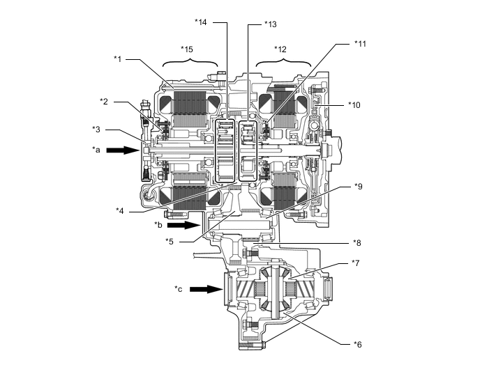
*1 Cooling Pipe *2 Rotation Sensor (for MG2) *3 Oil Pump *4 Counter Drive Gear (Compound Gear) *5 Counter Driven Gear *6 Differential *7 Differential Pre-torque Mechanism *8 Final Driven Gear *9 Final Drive Gear *10 Transaxle Damper (Transmission Input Damper Assembly) *11 Rotation Sensor (for MG1) *12 Generator (MG1) *13 Power Split Planetary Gear Unit *14 Motor Speed Reduction Planetary Gear Unit *15 Motor (MG2) - - *a Main Shaft *b 2nd Shaft *c 3rd Shaft - -
-