THEFT DETERRENT SYSTEM Theft Warning Siren Circuit
DESCRIPTION
The theft warning siren sounds if either of the following condition is met:
-
The theft deterrent system is in the alarm sounding state.
-
The theft warning siren is in the armed state when +B, GND or the communication line is open.
WIRING DIAGRAM
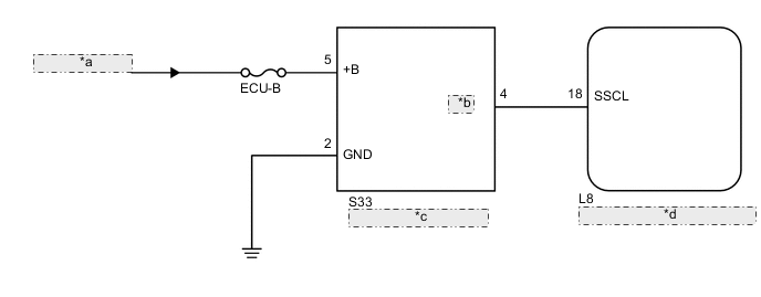
| *a | from Auxiliary Battery |
| *b | CONT |
| *c | Theft Warning Siren Assembly |
| *d | Main Body ECU (Multiplex Network Body ECU) |
CAUTION / NOTICE / HINT
Note
Inspect the fuses for circuits related to this system before performing the following inspection procedure.
PROCEDURE
-
PERFORM ACTIVE TEST USING GTS
-
Connect the GTS to the DLC3.
-
Turn the power switch to on (IG).
-
Turn the GTS on.
-
Enter the following menus: Body Electrical / Main Body / Active Test.
-
Perform the Active Test according to the display on the GTS.
Main Body Tester Display Test Part Control Range Diagnostic Note Security Horn2 Theft warning siren ON / OFF - OK The theft warning siren assembly sounds and stops correctly when operated using the GTS.
OK 
PROCEED TO NEXT SUSPECTED AREA SHOWN IN PROBLEM SYMPTOMS TABLE Click here
NG 
-
-
CHECK THEFT WARNING SIREN ASSEMBLY
-
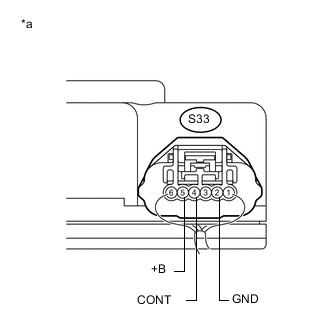
Text in Illustration *a Component with harness connected
(Theft Warning Siren Assembly)
Remove the theft warning siren assembly with harness connected Click here.
-
Measure the voltage according to the value(s) in the table below.
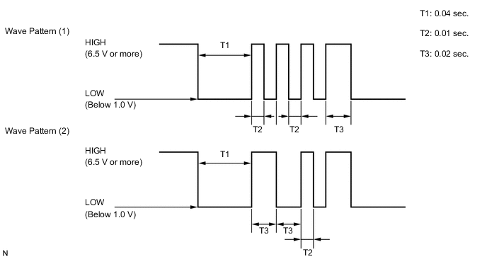
Standard Voltage Tester Connection Condition Specified Condition S33-5 (+B) - Body ground Power switch off 11 to 14 V S33-2 (GND) - Body ground Always Below 1 V S33-4 (CONT) - Body ground When switched from armed state or arming preparation state to disarmed state (1) or disarmed state (2) (*1) Wave pattern (1) shown in chart below When switched from arming preparation state to armed state (*2) Wave pattern (2) shown in chart below Normal condition (Except (*1) and (*2)) 11 to 14 V -
Wave pattern
NG
REPLACE THEFT WARNING SIREN ASSEMBLY Click here
OK
-
-
CHECK HARNESS AND CONNECTOR (MAIN BODY ECU - THEFT WARNING SIREN - BODY GROUND)
-
Disconnect the L8 main body ECU (multiplex network body ECU) connector.
-
Disconnect the S33 theft warning siren assembly connector.
-
Measure the resistance according to the value(s) in the table below.
Standard Resistance Tester Connection Condition Specified Condition L8-18 (SSCL) - S33-4 (CONT) Always Below 1 Ω L8-18 (SSCL) - Body ground Always 10 kΩ or higher S33-2 (GND) - Body ground Always Below 1 Ω
OK
REPLACE MAIN BODY ECU (MULTIPLEX NETWORK BODY ECU) Click here
NG
REPAIR OR REPLACE HARNESS OR CONNECTOR
-