OUTER MIRROR SWITCH INSPECTION
PROCEDURE
-
INSPECT OUTER MIRROR SWITCH ASSEMBLY
-
Check the mirror select switch and mirror surface adjust switch. (for RHD and w/o Double Locking System)
-
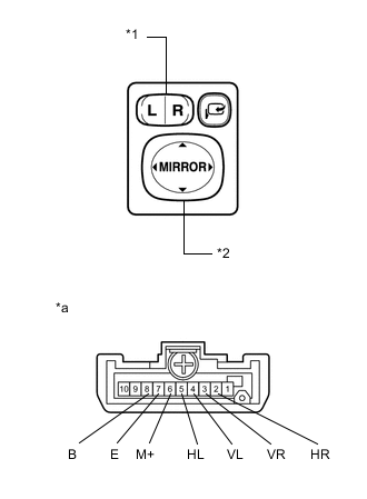
Text in Illustration *1 Mirror select switch *2 Mirror surface adjust switch *a Component without harness connected
(Outer Mirror Switch Assembly)
Turn the mirror select switch to the L position.
-
Measure the resistance according to the value(s) in the table below.
Standard Resistance (for left side) Tester Connection Condition Specified Condition 4 (VL) - 8 (B)
6 (M+) - 7 (E)
UP Below 1 Ω OFF 10 kΩ or higher 4 (VL) - 7 (E)
6 (M+) - 8 (B)
DOWN Below 1 Ω OFF 10 kΩ or higher 5 (HL) - 8 (B)
6 (M+) - 7 (E)
LEFT Below 1 Ω OFF 10 kΩ or higher 5 (HL) - 7 (E)
6 (M+) - 8 (B)
RIGHT Below 1 Ω OFF 10 kΩ or higher -
Turn the mirror select switch to the R position.
-
Measure the resistance according to the value(s) in the table below.
Standard Resistance (for right side) Tester Connection Condition Specified Condition 3 (VR) - 8 (B)
6 (M+) - 7 (E)
UP Below 1 Ω OFF 10 kΩ or higher 3 (VR) - 7 (E)
6 (M+) - 8 (B)
DOWN Below 1 Ω OFF 10 kΩ or higher 2 (HR) - 8 (B)
6 (M+) - 7 (E)
LEFT Below 1 Ω OFF 10 kΩ or higher 2 (HR) - 7 (E)
6 (M+) - 8 (B)
RIGHT Below 1 Ω OFF 10 kΩ or higher If the result is not as specified, replace the outer mirror switch assembly.
-
-
Check the mirror select switch and mirror surface adjust switch. (for LHD or w/ Double Locking System)
-
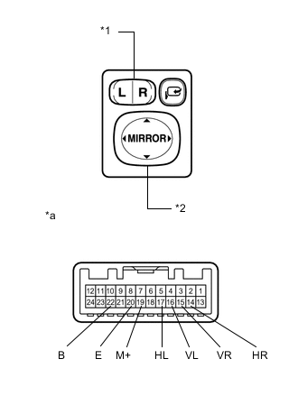
Text in Illustration *1 Mirror select switch *2 Mirror surface adjust switch *a Component without harness connected
(Outer Mirror Switch Assembly)
Turn the mirror select switch to the L position.
-
Measure the resistance according to the value(s) in the table below.
Standard Resistance (for left side) Tester Connection Condition Specified Condition 16 (VL) - 22 (B)
19 (M+) - 20 (E)
UP Below 1 Ω OFF 10 kΩ or higher 16 (VL) - 20 (E)
19 (M+) - 22 (B)
DOWN Below 1 Ω OFF 10 kΩ or higher 17 (HL) - 22 (B)
19 (M+) - 20 (E)
LEFT Below 1 Ω OFF 10 kΩ or higher 17 (HL) - 20 (E)
19 (M+) - 22 (B)
RIGHT Below 1 Ω OFF 10 kΩ or higher -
Turn the mirror select switch to the R position.
-
Measure the resistance according to the value(s) in the table below.
Standard Resistance (for right side) Tester Connection Condition Specified Condition 15 (VR) - 22 (B)
19 (M+) - 20 (E)
UP Below 1 Ω OFF 10 kΩ or higher 15 (VR) - 20 (E)
19 (M+) - 22 (B)
DOWN Below 1 Ω OFF 10 kΩ or higher 14 (HR) - 22 (B)
19 (M+) - 20 (E)
LEFT Below 1 Ω OFF 10 kΩ or higher 14 (HR) - 20 (E)
19 (M+) - 22 (B)
RIGHT Below 1 Ω OFF 10 kΩ or higher If the result is not as specified, replace the outer mirror switch assembly.
-
-
Check the mirror retract switch. (for RHD and w/o Double Locking System)
-
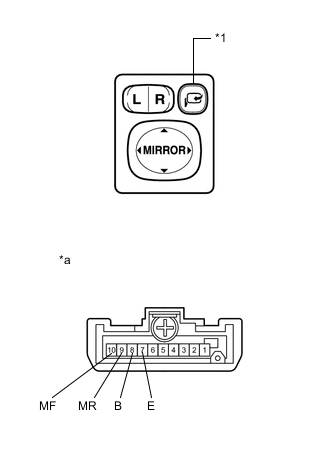
Text in Illustration *1 Mirror retract switch *a Component without harness connected
(Outer Mirror Switch Assembly)
Measure the resistance according to the value(s) in the table below.
Standard Resistance Tester Connection Condition Specified Condition 10 (MF) - 7 (E) Mirror retract switch retract position Below 1 Ω 9 (MR) - 8 (B) Below 1 Ω 10 (MF) - 8 (B) Mirror retract switch return position Below 1 Ω 9 (MR) - 7 (E) Below 1 Ω If the result is not as specified, replace the outer mirror switch assembly.
-
-
Check the mirror retract switch. (for LHD or w/ Double Locking System)
-
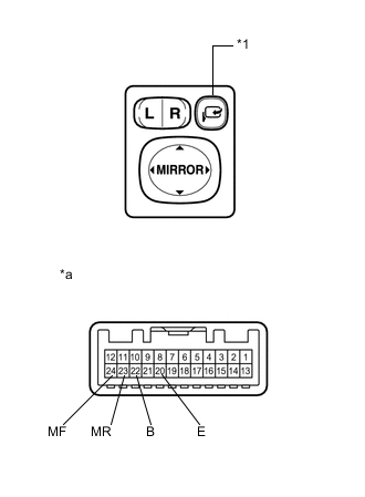
Text in Illustration *1 Mirror retract switch *a Component without harness connected
(Outer Mirror Switch Assembly)
Measure the resistance according to the value(s) in the table below.
Standard Resistance Tester Connection Condition Specified Condition 24 (MF) - 20 (E) Mirror retract switch retract position Below 1 Ω 23 (MR) - 22 (B) Below 1 Ω 24 (MF) - 22 (B) Mirror retract switch return position Below 1 Ω 23 (MR) - 20 (E) Below 1 Ω If the result is not as specified, replace the outer mirror switch assembly.
-
-