AUDIO AND VISUAL SYSTEM(for Radio and Display Type) Voice Guidance Circuit between Radio Receiver and Stereo Component Amplifier
| DTC Code | DTC Name |
|---|---|
| Voice Guidance Circuit between Radio Receiver and Stereo Component Amplifier |
DESCRIPTION
This circuit is used when the voice switch of the steering pad switch assembly is pushed.
Using this circuit, the radio and display receiver assembly sends signals to the stereo component amplifier assembly.
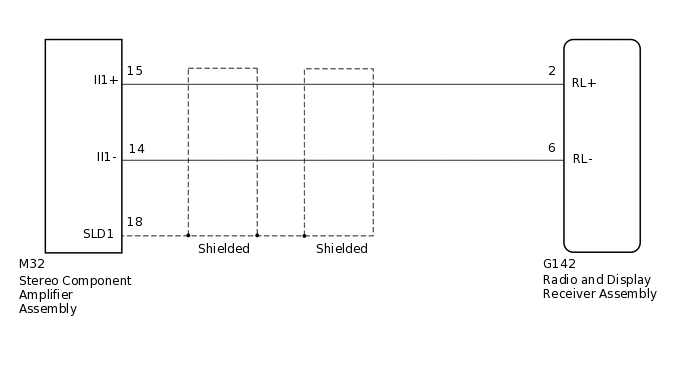
WIRING DIAGRAM
PROCEDURE
CHECK HARNESS AND CONNECTOR (RADIO AND DISPLAY RECEIVER ASSEMBLY - STEREO COMPONENT AMPLIFIER ASSEMBLY)
Disconnect the G142 radio and display receiver assembly connector.
Disconnect the M32 stereo component amplifier assembly connector.
Measure the resistance according to the value(s) in the table below.
Standard Resistance
Tester Connection
Condition
Specified Condition
G142-2 (RL+) - M32-15 (II1+)
Always
Below 1 Ω
G142-6 (RL-) - M32-14 (II1-)
Always
Below 1 Ω
M32-18 (SLD1) - Body ground
Always
10 kΩ or higher
G142-2 (RL+) - Body ground
Always
10 kΩ or higher
G142-6 (RL-) - Body ground
Always
10 kΩ or higher
Result
Proceed to
OK
NG
NG REPAIR OR REPLACE HARNESS OR CONNECTOR