POWER MIRROR CONTROL SYSTEM Mirror Heater does not Operate with Rear Defogger Switch
| DTC Code | DTC Name |
|---|---|
| Mirror Heater does not Operate with Rear Defogger Switch |
DESCRIPTION
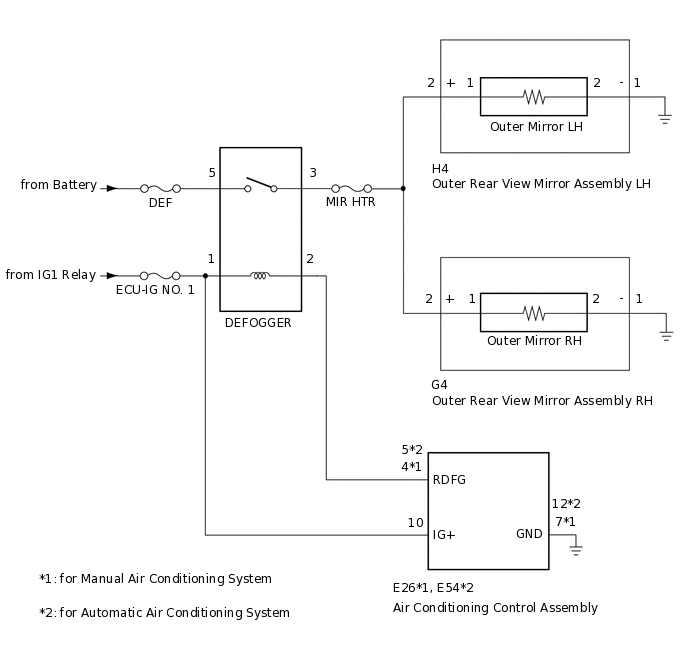
When the mirror heater switch (rear window defogger switch) on the heater control panel assembly is pressed, the operation signal is sent to the defogger relay via a direct line. When the defogger relay receives the signal, it turns on the defogger relay to operate the mirror heaters.
WIRING DIAGRAM
CAUTION / NOTICE / HINT
Inspect the fuses for circuits related to this system before performing the following procedure.
PROCEDURE
CHECK MIRROR HEATER FUNCTION
Check the mirror heater operation.
OK
The mirror heater operates normally.
Result
Result
Proceed to
Mirror heater operation on both mirrors is not normal
A
Mirror heater operation on RH side mirror is not normal
B
Mirror heater operation on LH side mirror is not normal
C
B CHECK HARNESS AND CONNECTOR (DEFOGGER RELAY - OUTER REAR VIEW MIRROR ASSEMBLY RH - BODY GROUND)Click here
C CHECK HARNESS AND CONNECTOR (DEFOGGER RELAY - OUTER REAR VIEW MIRROR ASSEMBLY LH - BODY GROUND)Click here
CHECK WINDOW DEFOGGER SYSTEM
Check the window defogger system operation.
OK
The window defogger system operates normally.
Result
Proceed to
OK
NG
CHECK HARNESS AND CONNECTOR (DEFOGGER RELAY - OUTER REAR VIEW MIRROR ASSEMBLY LH/RH)
-
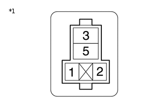
*1
Center Relay Block
Remove the DEFOGGER relay from center relay block.
Disconnect the G4 outer rear view mirror assembly RH connector.
Disconnect the H4 outer rear view mirror assembly LH connector.
Measure the resistance according to the value(s) in the table below.
Standard Resistance
Tester Connection
Condition
Specified Condition
Center relay block DEFOGGER relay terminal 3 - G4-2 (+)
Always
Below 1 Ω
Center relay block DEFOGGER relay terminal 3 - H4-2 (+)
Always
Below 1 Ω
Center relay block DEFOGGER relay terminal 3 or G4-2 (+) - Body Ground
Always
10 kΩ or higher
Center relay block DEFOGGER relay terminal 3 or H4-2 (+) - Body Ground
Always
10 kΩ or higher
Result
Proceed to
OK
NG
NG REPAIR OR REPLACE HARNESS OR CONNECTOR
-
CHECK HARNESS AND CONNECTOR (DEFOGGER RELAY - OUTER REAR VIEW MIRROR ASSEMBLY RH - BODY GROUND)
-
*1
Center Relay Block
Remove the DEFOGGER relay from center relay block.
Disconnect the G4 outer rear view mirror assembly RH connector.
Disconnect the H4 outer rear view mirror assembly LH connector.
Measure the resistance according to the value(s) in the table below.
Standard Resistance
Tester Connection
Condition
Specified Condition
Center relay block DEFOGGER relay terminal 3 - G4-2 (+)
Always
Below 1 Ω
G4-1 (-) - Body Ground
Always
Below 1 Ω
Center relay block DEFOGGER relay terminal 3 or G4-2 (+) - Body Ground
Always
10 kΩ or higher
Result
Proceed to
OK
NG
NG REPAIR OR REPLACE HARNESS OR CONNECTOR
-
INSPECT OUTER MIRROR RH (MIRROR HEATER)
Remove the outer mirror RH.
Inspect the outer mirror RH.
OK
Outer mirror RH is normal.
Result
Proceed to
OK
NG
CHECK HARNESS AND CONNECTOR (DEFOGGER RELAY - OUTER REAR VIEW MIRROR ASSEMBLY LH - BODY GROUND)
-
*1
Center Relay Block
Remove the DEFOGGER relay from the center relay block.
Disconnect the G4 outer rear view mirror assembly RH connector.
Disconnect the H4 outer rear view mirror assembly LH connector.
Measure the resistance according to the value(s) in the table below.
Standard Resistance
Tester Connection
Condition
Specified Condition
Center relay block DEFOGGER relay terminal 3 - H4-2 (+)
Always
Below 1 Ω
H4-1 (-) - Body Ground
Always
Below 1 Ω
Center relay block DEFOGGER relay terminal 3 or H4-2 (+) - Body Ground
Always
10 kΩ or higher
Result
Proceed to
OK
NG
NG REPAIR OR REPLACE HARNESS OR CONNECTOR
-
INSPECT OUTER MIRROR LH (MIRROR HEATER)
Remove the outer mirror LH.
Inspect the outer mirror LH.
OK
Outer mirror LH is normal.
Result
Proceed to
OK
NG