DYNAMIC RADAR CRUISE CONTROL SYSTEM Distance Control Switch Circuit
| DTC Code | DTC Name |
|---|---|
| Distance Control Switch Circuit |
DESCRIPTION
The distance control switch sets the vehicle-to-vehicle distance setting. The distance control switch is installed in the steering pad switch. The vehicle-to-vehicle distance setting can be changed by operating the distance control switch in the steering pad switch while the dynamic radar cruise control system is in operation.
WIRING DIAGRAM
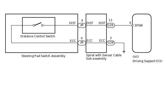
PROCEDURE
INSPECT STEERING PAD SWITCH ASSEMBLY (DISTANCE CONTROL SWITCH)
Remove the steering pad switch assembly
Measure the resistance according to the value(s) in the table below.
Standard Resistance
Tester Connection
Switch Condition
Specified Condition
4 (DIST) - 6 (ECC)
Distance control switch on
Below 2.5 Ω
4 (DIST) - 6 (ECC)
Distance control switch off
1 MΩ or higher
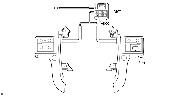
*1
Distance Control Switch
-
-
Result
Result
OK
NG
INSPECT SPIRAL WITH SENSOR CABLE SUB-ASSEMBLY
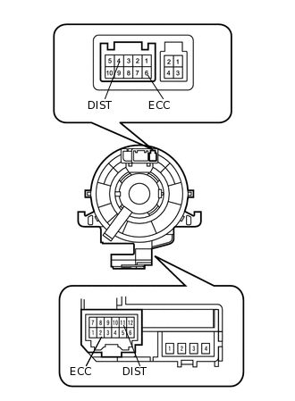
Remove the spiral with sensor cable sub-assembly
If there are any defects as follows, replace the spiral with sensor cable sub-assembly with a new one: scratches, cracks, dents or chips in the connector or spiral with sensor cable sub-assembly.
Check the spiral with sensor cable sub-assembly.
Set the spiral with sensor cable sub-assembly to the center position
Rotate the spiral with sensor cable sub-assembly 2.5 times clockwise and measure the resistance according to the value(s) in the table below. Then rotate the spiral with sensor cable sub-assembly 5 times counterclockwise and measure the resistance according to the value(s) in the table below.
Note:As the spiral with sensor cable sub-assembly may break, do not rotate the spiral with sensor cable sub-assembly more than the specified amount.
Standard Resistance
Tester Connection
Condition
Specified Condition
4 (DIST) - 11 (DIST)
Always
Below 1 Ω
6 (ECC) - 2 (ECC)
Always
Below 1 Ω
Set the spiral with sensor cable sub-assembly to the center position and rotate the spiral with sensor cable sub-assembly 2.5 times clockwise. Then, while rotating the spiral with sensor cable sub-assembly 5 times counterclockwise, measure the resistance according to the value(s) in the table below.
Standard Resistance
Tester Connection
Condition
Specified Condition
4 (DIST) - 11 (DIST)
Always
Below 1 Ω
6 (ECC) - 2 (ECC)
Always
Below 1 Ω
Result
Result
OK
NG
CHECK HARNESS AND CONNECTOR (SPIRAL WITH SENSOR CABLE SUB-ASSEMBLY - DRIVING SUPPORT ECU AND BODY GROUND)
Disconnect the G28 spiral with sensor cable sub-assembly connector.
Disconnect the G43 driving support ECU connector.
Measure the resistance according to the value(s) in the table below.
Standard Resistance
Tester Connection
Condition
Specified Condition
G28-11 (DIST) - G43-6 (SPSW)
Always
Below 1 Ω
G28-2 (ECC) - Body ground
Always
Below 1 Ω
G28-11 (DIST) - Body ground
Always
10 kΩ or higher
Result
Result
OK
NG
NG REPAIR OR REPLACE HARNESS OR CONNECTOR