AIR CONDITIONING SYSTEM(for Manual Air Conditioning System) Heater Control Switch Circuit
| DTC Code | DTC Name |
|---|---|
| Heater Control Switch Circuit |
DESCRIPTION
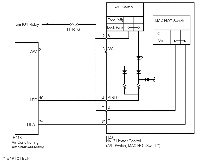
The No. 3 heater control sub-assembly is powered through the HTR-IG fuse. The No. 3 heater control sub-assembly transmits the operation signals of each switch to the air conditioning amplifier.
WIRING DIAGRAM
CAUTION / NOTICE / HINT
Inspect the fuses for circuits related to this system before performing the following inspection procedure.
PROCEDURE
INSPECT NO. 3 HEATER CONTROL SUB-ASSEMBLY
-
Remove the No. 3 heater control sub-assembly (Click here).
Measure the resistance according to the value(s) in the table below.
Standard Resistance
Tester Connection
Switch Condition
Specified Condition
2 (B) - 3 (A/C)
A/C switch on
Below 1 Ω
2 (B) - 3 (A/C)
A/C switch off
10 kΩ or higher
7 (B) - 8 (E)*
Temperature setting MAX HOT
Below 1 Ω
7 (B) - 8 (E)*
Temperature setting not MAX HOT
10 kΩ or higher
*: w/ PTC heater
Apply battery voltage to the No. 3 heater control sub-assembly and check that the indicator light comes on.
OK
Measurement Condition
Specified Condition
Battery positive (+) → Terminal 3
Battery negative (-) → Terminal 4
Indicator light comes on
Table 1. Text in Illustration *1
w/ PTC Heater
-
CHECK HARNESS AND CONNECTOR (NO. 3 HEATER CONTROL - BATTERY)
-
Disconnect the H23 heater control connector.
Measure the voltage according to the value(s) in the table below.
Standard Voltage
Tester Connection
Switch Condition
Specified condition
H23-2 (B) - Body ground
Ignition switch ON
11 to 14 V
H23-2 (B) - Body ground
Ignition switch off
Below 1 V
H23-7 (B) - Body ground*
Ignition switch ON
11 to 14 V
H23-7 (B) - Body ground*
Ignition switch off
Below 1 V
*: w/ PTC heater
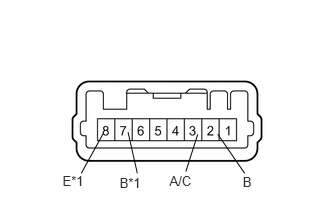
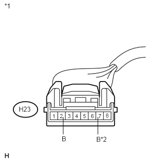
Table 2. Text in Illustration *1
Front view of wire harness connector
(to No. 3 Heater Control Sub-assembly)
*2
w/ PTC Heater
REPAIR OR REPLACE HARNESS OR CONNECTOR
-
CHECK HARNESS AND CONNECTOR (NO. 3 HEATER CONTROL - AIR CONDITIONING AMPLIFIER)
-
Disconnect the H118 amplifier connector.
Disconnect the H23 heater control connector.
Measure the resistance according to the value(s) in the table below.
Standard Resistance
Tester Connection
Condition
Specified condition
H23-3 (A/C) - H118-2 (A/C)
Always
Below 1 Ω
H23-4 (AIND) - H118-16 (LED)
Always
Below 1 Ω
H23-8 (E) - H118-3 (HEAT)*
Always
Below 1 Ω
H23-3 (A/C) - Body ground
Always
10 kΩ or higher
H23-4 (AIND) - Body ground
Always
10 kΩ or higher
H23-8 (E) - Body ground*
Always
10 kΩ or higher
*: w/ PTC heater
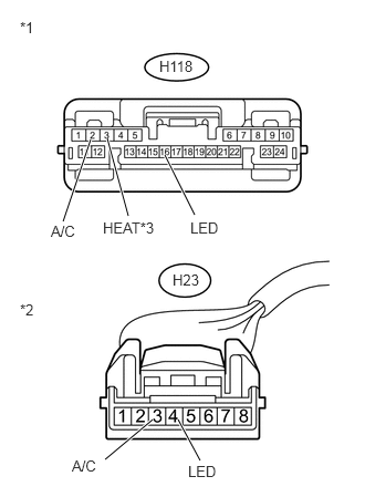
Table 3. Text in Illustration *1
Front view of wire harness connector
(to Air Conditioning Amplifier Assembly)
*2
Front view of wire harness connector
(to No. 3 Heater Control Sub-assembly)
*3
w/ PTC Heater
REPAIR OR REPLACE HARNESS OR CONNECTOR
-