AUTOMATIC TRANSAXLE UNIT INSPECTION

PROCEDURE
-
INSPECT TRANSMISSION OIL CLEANER MAGNET
-
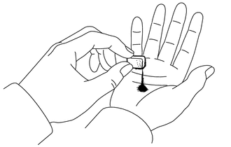
Use the removed transmission oil cleaner magnets to collect any steel chips. Examine the chips and particles in the transaxle housing and on the transmission oil cleaner magnets to determine what type of wear might be found in the automatic transaxle assembly.
Result Steel (magnetic) Bearing, gear and plate wear Brass (non-magnetic) Bushing wear
-
-
INSPECT INPUT SHAFT END PLAY
-
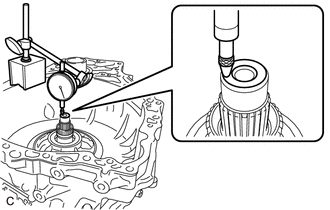
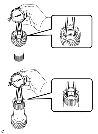
Using a dial indicator, measure the input shaft end play.
Input Shaft End Play 0.255 to 1.103 mm (0.0100 to 0.0434 in.)
-
-
INSPECT FORWARD MULTIPLE DISC CLUTCH DISC
-
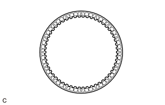
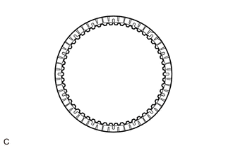
Check if the contact surfaces of the forward multiple disc clutch discs, forward multiple disc clutch plates and forward clutch flange are worn or burnt.
If necessary, replace them.
Note
-
If the lining of any forward multiple disc clutch disc is peeled off or discolored, or even if part of the groove is damaged, replace all of the forward multiple disc clutch discs.
-
Before installing new forward multiple disc clutch discs, soak them in ATF for at least 2 hours.
-
-
-
INSPECT NO. 2 CLUTCH DISC
-
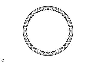
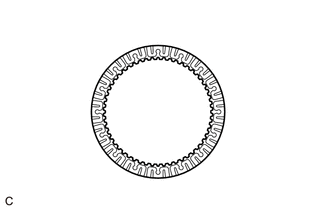
Check if the contact surfaces of the No. 2 clutch discs, No. 2 clutch plates and direct clutch flange are worn or burnt.
If necessary, replace them.
Note
-
If the lining of any No. 2 clutch disc is peeled off or discolored, or even if part of the groove is damaged, replace all of the No. 2 clutch discs.
-
Before installing new No. 2 clutch discs, soak them in ATF for at least 2 hours.
-
-
-
INSPECT NO. 3 CLUTCH DISC
-
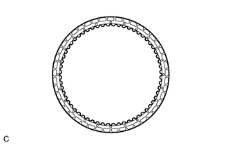
Check if the contact surfaces of the No. 3 clutch discs, No. 3 clutch plates and reverse clutch flange are worn or burnt.
If necessary, replace them.
Note
-
If the lining of any No. 3 clutch disc is peeled off or discolored, or even if part of the groove is damaged, replace all of the No. 3 clutch discs.
-
Before installing new No. 3 clutch discs, soak them in ATF for at least 2 hours.
-
-
-
INSPECT NO. 4 CLUTCH DISC
-
Check if the contact surfaces of the No. 4 clutch discs, No. 4 clutch plates and No. 1 underdrive clutch flange are worn or burnt.
If necessary, replace them.
Note
-
If the lining of any No. 4 clutch disc is peeled off or discolored, or even if part of the groove is damaged, replace all of the No. 4 clutch discs.
-
Before installing new No. 4 clutch discs, soak them in ATF for at least 2 hours.
-
-
-
INSPECT 1ST AND REVERSE BRAKE CLUTCH DISC
-
Check if the contact surfaces of the 1st and reverse brake clutch discs, 1st and reverse brake clutch plates and 1st and reverse brake flanges are worn or burnt.
If necessary, replace them.
Note
-
If the lining of any 1st and reverse brake clutch disc is peeled off or discolored, or even if part of the groove is damaged, replace all of the 1st and reverse brake clutch discs.
-
Before installing new 1st and reverse brake clutch discs, soak them in ATF for at least 2 hours.
-
-
-
INSPECT REAR PLANETARY SUN GEAR SUB-ASSEMBLY
-
Using a caliper gauge, measure the inside diameter of the bushings of the rear planetary sun gear sub-assembly.
Standard Inside Diameter 24.287 to 24.313 mm (0.956 to 0.957 in.) Maximum Inside Diameter 24.313 mm (0.957 in.) If the inside diameter is greater than the maximum, replace the rear planetary sun gear sub-assembly.
-
-
INSPECT FRONT PLANETARY GEAR ASSEMBLY
-
Using a feeler gauge, measure the clearance between the front planetary gear assembly and each pinion gear.
Standard Clearance 0.2 to 0.6 mm (0.00787 to 0.0236 in.) If the clearance is not as specified, replace the front planetary gear assembly.
-
Using a feeler gauge, measure the clearance between the front planetary gear assembly and each pinion gear.
Standard Clearance 0.2 to 0.6 mm (0.00787 to 0.0236 in.) If the clearance is not as specified, replace the front planetary gear assembly.
-
-
INSPECT REAR PLANETARY GEAR ASSEMBLY
-
Using a caliper gauge, measure the inside diameter of the bushings of the planetary sun gear sub-assembly.
Standard Inside Diameter 33.286 to 33.312 mm (1.31047 to 1.31149 in.) Maximum Inside Diameter 33.312 mm (1.31149 in.) If the inside diameter is greater than the maximum, replace the rear planetary gear assembly.
-
Using a feeler gauge, measure the clearance between the rear planetary gear assembly and each pinion gear.
Standard Clearance 0.19 to 0.77 mm (0.00748 to 0.0303 in.) If the clearance is not as specified, replace the rear planetary gear assembly.
-
Using a feeler gauge, measure the clearance between the rear planetary gear assembly and each pinion gear.
Standard Clearance 0.19 to 0.77 mm (0.00748 to 0.0303 in.) If the clearance is not as specified, replace the rear planetary gear assembly.
-
-
INSPECT ONE-WAY CLUTCH ASSEMBLY
-
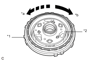
*1 One-way Clutch Assembly *2 Rear Planetary Gear Assembly *a Lock *b Free Temporarily install the one-way clutch assembly to the rear planetary gear assembly.
-
Make sure that the one-way clutch assembly locks when turned counterclockwise and turns freely when turned clockwise.
If the one-way clutch assembly does not operate properly, replace it.
-
-
INSPECT B-1 BRAKE PISTON ROD STROKE
-
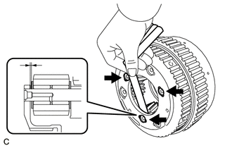
Using a caliper gauge, measure the stroke of the B-1 brake piston rod while applying compressed air (approximately 400 kPa (4.1 kgf/cm2, 58 psi)).
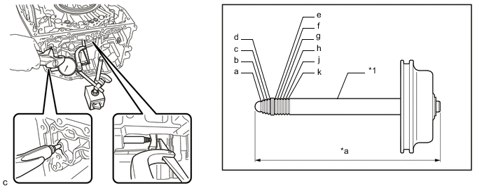
*1 B-1 Brake Piston Rod - - *a B-1 Brake Piston Rod Length - - Standard Stroke 5.5 to 6.0 mm (0.217 to 0.236 in.) If the stroke is not as specified, select an appropriate B-1 brake piston so that the stroke will be within the specified range.
B-1 Brake Piston Rod Length Mark (Groove) Length (mm (in.)) None 102.8 (4.05) a 103.05 (4.06) a, b 103.3 (4.07) a, b, c 103.55 (4.08) a, b, c, d 103.8 (4.09) a, b, c, d, e 104.05 (4.10) a, b, c, d, e, f 104.3 (4.11) a, b, c, d, e, f, g 104.55 (4.12) a, b, c, d, e, f, g, h 104.8 (4.13) a, b, c, d, e, f, g, h, j 105.05 (4.14) a, b, c, d, e, f, g, h, j, k 105.3 (4.15)
-
-
INSPECT CLUTCH RETURN WITH RETAINER SPRING SUB-ASSEMBLY
-
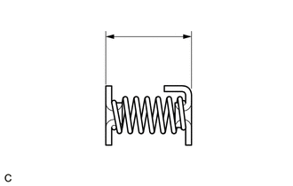
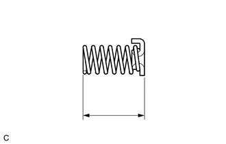
Using a vernier caliper, measure the free length of the clutch return with retainer spring sub-assembly including the spring seats.
Standard Free Length 14.62 mm (0.576 in.) If the free length is shorter than the standard free length, replace the clutch return with retainer spring sub-assembly.
-
-
INSPECT 1ST AND REVERSE BRAKE RETURN SPRING SUB-ASSEMBLY
-
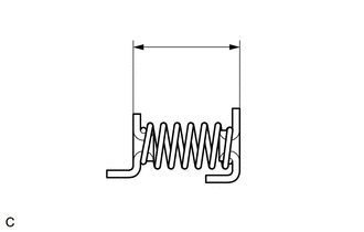
Using a vernier caliper, measure the free length of the 1st and reverse brake return spring sub-assembly including the spring seat.
Standard Free Length 19.01 mm (0.748 in.) If the free length is shorter than the standard free length, replace the 1st and reverse brake return spring sub-assembly.
-
-
INSPECT UNDER DRIVE RETURN WITH RETAINER SPRING SUB-ASSEMBLY
-
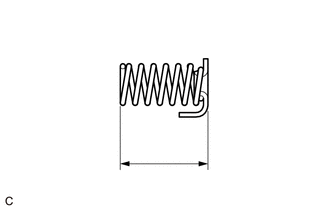
Using a vernier caliper, measure the free length of the under drive return with retainer spring sub-assembly including the spring seats.
Standard Free Length 17.26 mm (0.680 in.) If the free length is shorter than the standard free length, replace the under drive return with retainer spring sub-assembly.
-
-
INSPECT FORWARD CLUTCH RETURN SPRING SUB-ASSEMBLY
-
Using a vernier caliper, measure the free length of the forward clutch return spring sub-assembly including the spring seat.
Standard Free Length 15.38 mm (0.606 in.) If the free length is shorter than the standard free length, replace the forward clutch return spring sub-assembly.
-
-
INSPECT CLEARANCE OF C-3 CLUTCH
-
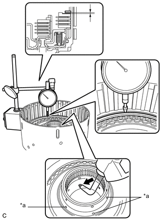
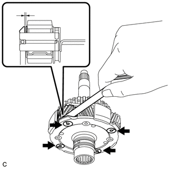
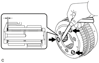
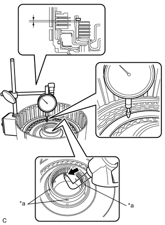
*a ATF Hole Using a dial indicator, measure the clearance of the C-3 clutch while applying compressed air (approximately 200 kPa (2.0 kgf/cm2, 29 psi)).
Pack Clearance 0.3 to 0.5 mm (0.0118 to 0.0197 in.) Tech Tips
Measure the clearance at 3 points where the clutch piston diameter is approximately 140 mm (5.51 in.) and calculate the average.
If the clearance is not as specified, select an appropriate reverse clutch flange so that the clearance will be within the specified range.
Tech Tips
-
There are 11 reverse clutch flanges of different thicknesses available.
-
Make sure to cover the ATF holes shown in the illustration.
Reverse Clutch Flange Thickness Part Number Thickness
(mm (in.))
Mark 35649-48030 3.0 (0.118) R 35649-48100 3.05 (0.120) 2 35649-48040 3.1 (0.122) S 35649-48110 3.15 (0.124) A 35649-48050 3.2 (0.126) T 35649-48260 3.25 (0.128) AA 35649-48060 3.3 (0.130) U 35649-48270 3.35 (0.132) BB 35649-48070 3.4 (0.134) W 35649-48280 3.45 (0.136) CC 35649-48080 3.5 (0.138) X -
-
-
INSPECT CLEARANCE OF C-4 CLUTCH
-
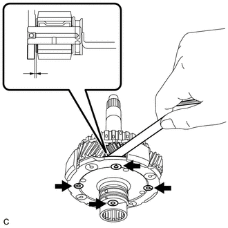
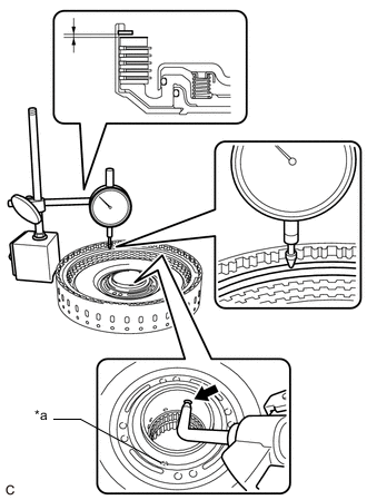
*a ATF Hole Using a dial indicator, measure the clearance of the C-4 clutch while applying compressed air (approximately 400 kPa (4.1 kgf/cm2, 58 psi)).
Pack Clearance 0.4 to 0.6 mm (0.0157 to 0.0236 in.) Tech Tips
Measure the clearance at 3 points where the C-4 clutch piston diameter is approximately 140 mm (5.51 in.) and calculate the average.
If the clearance is not as specified, select an appropriate No. 1 underdrive clutch flange so that the clearance will be within the specified range.
Tech Tips
-
There are 12 No. 1 underdrive clutch flanges of different thicknesses available.
-
Make sure to cover the ATF hole shown in the illustration.
No. 1 Underdrive Clutch Flange Thickness Part Number Thickness
(mm (in.))
Mark 34265-48010 3.0 (0.118) 0 34265-48020 3.1 (0.122) 1 34265-48100 3.15 (0.124) A 34265-48030 3.2 (0.126) 2 34265-48110 3.25 (0.128) B 34265-48040 3.3 (0.130) 3 34265-48120 3.35 (0.132) C 34265-48050 3.4 (0.134) 4 34265-48060 3.5 (0.138) 5 34265-48070 3.6 (0.142) 6 34265-48080 3.7 (0.146) 7 34265-48090 3.8 (0.150) 8 -
-
-
INSPECT CLEARANCE OF C-1 CLUTCH
-
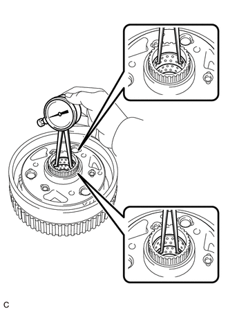
*a ATF Hole Using a dial indicator, measure the clearance of the C-1 clutch while applying compressed air (approximately 200 kPa (2.0 kgf/cm2, 29 psi)).
Piston Stroke 1.0 to 1.2 mm (0.0394 to 0.0472 in.) Tech Tips
Measure the clearance at 3 points where the forward clutch piston diameter is approximately 140 mm (5.51 in.) and calculate the average.
If the clearance is not as specified, select an appropriate forward clutch flange so that the clearance will be within the specified range.
Tech Tips
-
There are 10 forward clutch flanges of different thicknesses available.
-
Make sure to cover the ATF holes shown in the illustration.
Forward Clutch Flange Thickness Part Number Thickness (mm (in.)) 35635-48010 4.1 (0.161) 35635-48020 4.2 (0.165) 35635-48030 4.3 (0.169) 35635-48040 4.4 (0.173) 35635-48090 4.45 (0.175) 35635-48050 4.5 (0.177) 35635-48100 4.55 (0.179) 35635-48060 4.6 (0.181) 35635-48110 4.65 (0.183) 35635-48070 4.7 (0.185) -
-
-
INSPECT CLEARANCE OF NO. 2 BRAKE
-
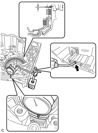
Using a dial indicator, measure the clearance of the No. 2 brake while applying compressed air (approximately 200 kPa (2.0 kgf/cm2, 29 psi)).
Pack Clearance 0.5 to 0.7 mm (0.0197 to 0.0276 in.) Tech Tips
Measure the clearance at 3 points where the 1st and reverse brake piston diameter is approximately 140 mm (5.51 in.) and calculate the average.
If the clearance is not as specified, select an appropriate 1st and reverse brake flange so that the clearance will be within the specified range.
Tech Tips
There are 8 1st and reverse brake flanges of different thicknesses available.
1st and Reverse Brake Flange Thickness Part Number Thickness
(mm (in.))
Mark 35676-48020 4.7 (0.185) 47 35676-48030 4.8 (0.189) 48 35676-48040 4.9 (0.193) 49 35676-48050 5.0 (0.197) 50 35676-48060 5.1 (0.201) 51 35676-48070 5.2 (0.205) 52 35676-48080 5.3 (0.209) 53 35676-48090 5.4 (0.213) 54
-
-
INSPECT CLEARANCE OF C-2 CLUTCH
-
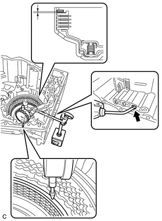
Using a dial indicator, measure the clearance of the C-2 clutch while applying compressed air (approximately 400 kPa (4.1 kgf/cm2, 58 psi)).
Piston Stroke 0.6 to 0.8 mm (0.0236 to 0.0315 in.) Tech Tips
Measure the clearance at 3 points where the C-2 clutch piston diameter is approximately 140 mm (5.51 in.) and calculate the average.
If the clearance is not as specified, select an appropriate direct clutch flange so that the clearance will be within the specified range.
Tech Tips
There are 11 direct clutch flanges of different thicknesses available.
Direct Clutch Flange Thickness Part Number Thickness (mm (in.)) 35675-48010 2.5 (0.0984) 35675-48020 2.6 (0.102) 35675-48030 2.7 (0.106) 35675-48040 2.8 (0.110) 35675-48090 2.85 (0.112) 35675-48050 2.9 (0.114) 35675-48100 2.95 (0.116) 35675-48060 3.0 (0.118) 35675-48110 3.05 (0.120) 35675-48070 3.1 (0.122) 35675-48080 3.2 (0.126)
-