REAR WHEEL ALIGNMENT ADJUSTMENT
CAUTION / NOTICE / HINT
Note
If the wheel alignment has been adjusted, and if suspension or underbody components have been removed/installed or replaced, be sure to perform the following initialization procedure in order for the system to function normally:
Perform zero point calibration of the yaw rate and acceleration sensor and test mode inspection Click here.
PROCEDURE
-
INSPECT TIRES
-
MEASURE VEHICLE HEIGHT
-
INSPECT TOE-IN
Note
Inspect while the vehicle is unloaded.
-
Bounce the vehicle up and down at the corners to stabilize the suspension.
-
Release the parking brake and move the shift lever to N.
-
Push the vehicle straight ahead approximately 5 m (16.4 ft.). (Step B)
-
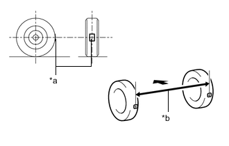
Text in Illustration *a Tread Center Mark *b Dimension B 
Front of the Vehicle Put tread center marks on the rearmost points of the rear wheels and measure the distance between the marks (dimension B).
-
Slowly push the vehicle straight ahead to cause the rear wheels to rotate 180°. Use the rear tire valve as a reference point.
Tech Tips
Do not allow the wheels to rotate more than 180°. If the wheels rotate more than 180°, perform the procedure from Step B again.
-
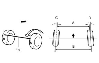
Text in Illustration *a Dimension A Front of the Vehicle Measure the distance between the tread center marks on the front of the rear wheels (dimension A).
Toe-in (Unloaded Vehicle) Specified Condition C + D: 0°10' +/- 0°15' (0.16° +/- 0.24°) B - A: 2.0 +/- 3.0 mm(0.0787 +/- 0.1181 in.) Tech Tips
Measure "B - A" only when "C + D" cannot be measured.
If the toe-in is not within the specified range, adjust it at the toe control link sub-assembly.
-
-
ADJUST TOE-IN
-
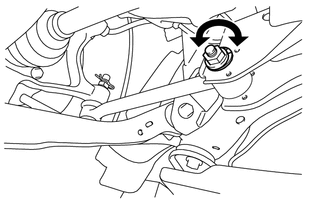
Loosen the toe adjust cam nut.
-
Turn the adjust cams by an equal amount to adjust the toe-in.
Toe-in (Unloaded Vehicle) Specified Condition C + D: 0°10' +/- 0°15' (0.16° +/- 0.24°) B - A: 2.0 +/- 3.0 mm(0.0787 +/- 0.1181 in.) Tech Tips
-
Try to adjust the toe-in to the center value.
-
The toe-in will change by approximately 5.2 mm (0.205 in.) for each gradation of the cam.
-
-
Tighten the toe adjust cam nut.
- Torque:
- 100 N*m { 1020 kgf*cm, 74 ft.*lbf }
-
-
INSPECT CAMBER
-
Remove the center wheel ornament.
-
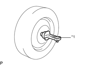
Text in Illustration *1 Camber-caster-kingpin Gauge Install a camber-caster-kingpin gauge at the center of the axle hub or drive shaft.
-
Inspect the camber.
Camber (Unloaded Vehicle) Camber Inclination Right-left Difference -1°12' +/- 45'
(-1.20° +/- 0.75°)
45' (0.75°) or less If the measured value is not within the specified range, inspect the suspension parts for damage and wear. Replace parts as necessary because camber cannot be properly adjusted with any damaged or worn parts.
-
Remove the camber-caster-kingpin gauge.
-
Install the center wheel ornament.
-
-
INSPECT REAR SUSPENSION
-
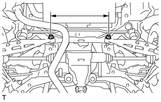
Inspect the rear suspension member.
-
Measure the distance between the centers of the 2 installation bolts of the rear No. 2 suspension arm assembly LH and RH
Standard distance 454.5 to 460.5 mm (17.89 to 18.13 in.) If the distance is not within the specified range, replace the rear suspension member.
-
-
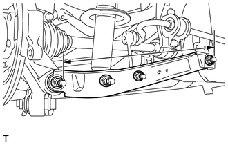
Inspect the rear No. 2 suspension arm assembly.
-
Measure the distance between the centers of the 2 installation bolts of the rear No. 2 suspension arm assembly.
Standard distance 448.9 to 452.9 mm (17.67 to 17.83 in.) If the distance is not within the specified range, replace the rear No. 2 suspension arm assembly.
-
-
Inspect and adjust the toe-in and camber.
-
Inspect the toe-in and camber.
Inspect the toe-in and camber. If the values are not within the specified ranges, adjust the installation bolt holding the rear suspension member to the vehicle body, or the bolt holding the upper control arm and rear suspension arm so that the values fall within the specified ranges.
-
-
-
PLACE FRONT WHEELS FACING STRAIGHT AHEAD
-
VSC SENSOR NEUTRAL MEMORIZATION
-
HEIGHT CONTROL SENSOR SIGNAL INITIALIZE (w/ HID Headlight System)
-
ADJUST HEADLIGHT AIMING (w/ HID Headlight System)