SIDE TURN SIGNAL LIGHT ASSEMBLY REMOVAL
CAUTION / NOTICE / HINT
The necessary procedures (adjustment, calibration, initialization, or registration) that must be performed after parts are removed and installed, or replaced during side turn signal light assembly removal/installation are shown below.
| Replaced Part or Performed Procedure | Necessary Procedure | Effect/Inoperative Function when Necessary Procedure not Performed | Link |
|---|---|---|---|
|
Side television camera view adjustment | Panoramic view monitor system |
Tech Tips
-
Use the same procedure for the RH side and LH side.
-
The following procedure is for the LH side.
PROCEDURE
-
REMOVE OUTER MIRROR
-
REMOVE OUTER MIRROR COVER WITH OUTER MIRROR HOLE COVER (w/o Panoramic View Monitor System)
-
REMOVE OUTER MIRROR COVER (w/o Panoramic View Monitor System)
-
REMOVE OUTER MIRROR COVER (w/ Panoramic View Monitor System)
-
REMOVE OUTER MIRROR HOLE COVER WITH SIDE TELEVISION CAMERA ASSEMBLY (w/ Panoramic View Monitor System)
-
REMOVE SIDE TURN SIGNAL LIGHT ASSEMBLY
-
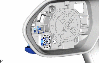
Disengage the 2 claws.
-
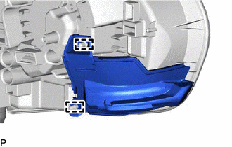
Disengage the 2 guides to separate the side turn signal light assembly.
-
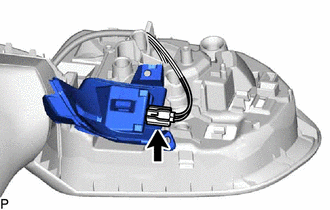
Disconnect the connector to remove the side turn signal light assembly.
-