LIGHTING SYSTEM Daytime Running Light Relay Circuit
DESCRIPTION
The main body ECU (multiplex network body ECU) controls the daytime running lights.
WIRING DIAGRAM
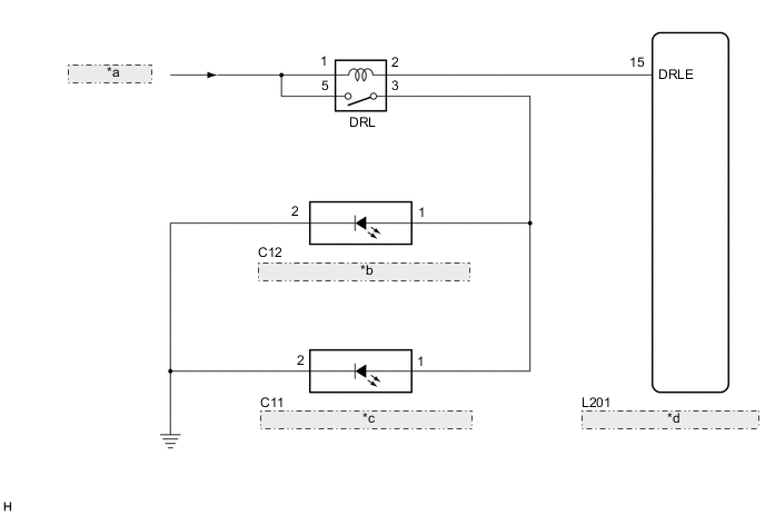
| *a | from DRL Fuse |
| *b | Daytime Running Light Assembly LH |
| *c | Daytime Running Light Assembly RH |
| *d | Main Body ECU (Multiplex Network Body ECU) |
CAUTION / NOTICE / HINT
Note
Inspect the fuses for circuits related to this system before performing the following inspection procedure.
PROCEDURE
-
PERFORM ACTIVE TEST USING GTS
-
Connect the GTS to the DLC3.
-
Turn the power switch on (IG).
-
Turn the GTS on.
-
Enter the following menus: Body Electrical / Main Body / Active Test.
-
Check that the daytime running lights operate.
Main Body Tester Display Test Part Control Range Diagnostic Note Daytime Running Light Daytime running lights ON/OFF - OK Daytime running lights illuminate.
OK 
PROCEED TO NEXT SUSPECTED AREA SHOWN IN PROBLEM SYMPTOMS TABLE Click here
NG 
-
-
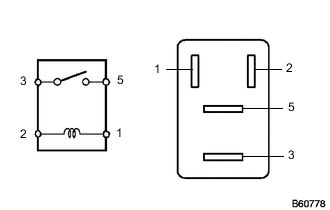
INSPECT DRL RELAY
-
Remove the DRL relay from the engine room relay block and junction block assembly.
-
Measure the resistance according to the value(s) in the table below.
Standard Resistance Tester Connection Condition Specified Condition 3 - 5 Voltage is not applied between terminals 1 and 2 10 kΩ or higher 3 - 5 Voltage is applied between terminals 1 and 2 Below 1 Ω
NG
REPLACE DRL RELAY
OK
-
-
CHECK HARNESS AND CONNECTOR (AUXILIARY BATTERY - DRL RELAY)
-
Measure the voltage according to the value(s) in the table below.
Standard Voltage Tester Connection Condition Specified Condition Relay terminal 1 - Body ground Power switch off 11 to 14 V Relay terminal 5 - Body ground Power switch off 11 to 14 V
NG
REPAIR OR REPLACE HARNESS OR CONNECTOR
OK
-
-
CHECK HARNESS AND CONNECTOR (DRL RELAY - MAIN BODY ECU)
-
Disconnect the L201 main body ECU (multiplex network body ECU) connector.
-
Measure the resistance according to the value(s) in the table below.
Standard Resistance Tester Connection Condition Specified Condition Relay terminal 2 - L201-15 (DRLE) Always Below 1 Ω L201-15 (DRLE) - Body ground Always 10 kΩ or higher
NG
REPAIR OR REPLACE HARNESS OR CONNECTOR
OK
-
-
CHECK HARNESS AND CONNECTOR (DRL RELAY - DAYTIME RUNNING LIGHT ASSEMBLY AND BODY GROUND)
-
Disconnect the C11 daytime running light assembly RH connector.
-
Disconnect the C12 daytime running light assembly LH connector.
-
Measure the resistance according to the value(s) in the table below.
Standard Resistance Tester Connection Condition Specified Condition Relay terminal 3 - C11-1 Always Below 1 Ω Relay terminal 3 - C12-1 Always Below 1 Ω Relay terminal 3 - Body ground Always 10 kΩ or higher C11-2 - Body ground Always Below 1 Ω C12-2 - Body ground Always Below 1 Ω
OK
REPLACE MAIN BODY ECU (MULTIPLEX NETWORK BODY ECU) Click here
NG
REPAIR OR REPLACE HARNESS OR CONNECTOR
-