SFI SYSTEM, Diagnostic DTC:P0336
| DTC Code | DTC Name |
|---|---|
| P0336 | Crankshaft Position Sensor "A" Circuit Range / Performance |
DESCRIPTION
The crankshaft position sensor monitors the stop position and performs start control from the position of the stopped crankshaft. Moreover, the crankshaft position sensor contains a function which detects reverse rotation to correctly detect the stop position when the engine rotates reversely.
When a malfunction occurs in the reverse rotation detection function, stop and start system is disabled.
DTC No. |
Detection Item |
DTC Detection Condition |
Trouble Area |
MIL |
Memory |
|---|---|---|---|---|---|
P0336 |
Crankshaft Position Sensor "A" Circuit Range / Performance |
When one of the following conditions is met (1 trip detection logic):
|
|
Comes on |
DTC stored |
MONITOR DESCRIPTION
When one of the following malfunctions is detected, P0336 is output.
An engine reverse signal is detected for 4 seconds while the engine is cranking or runnning normally at 900 rpm or higher.
The case the pulse width of the crankshaft position sensor is detected to have exceededthe threshold for 4 seconds while the engine is running normally at 900 rpm or higher.
The input signal voltage of the crankshaft position sensor continues at 4.7 V for 4 seconds while the engine runnning.
CONFIRMATION DRIVING PATTERN
Connect the GTS to the DLC3.
Turn the ignition switch to ON and turn the GTS on.
Clear the DTCs (even if no DTCs are stored, perform the clear DTC procedure).
Turn the ignition switch off and wait for at least 30 seconds.
Turn the ignition switch to ON and turn the GTS on.
Start the engine.
Idle the engine for 20 seconds or more.
Enter the following menus: Powertrain / Engine and ECT / Trouble Codes.
Read the pending DTCs.
Tip:If a pending DTC is output, the system is malfunctioning.
If a pending DTC is not output, perform the following procedure.
Enter the following menus: Powertrain / Engine and ECT / Utility / All Readiness.
Input the DTC: P0336.
Check the DTC judgment result.
GTS Display
Description
NORMAL
DTC judgment completed
System normal
ABNORMAL
DTC judgment completed
System abnormal
INCOMPLETE
DTC judgment not completed
Perform driving pattern after confirming DTC enabling conditions
N/A
Unable to perform DTC judgment
Number of DTCs which do not fulfill DTC preconditions has reached ECU memory limit
Tip:If the judgment result shows NORMAL, the system is normal.
If the judgment result shows ABNORMAL, the system has a malfunction.
If the judgment result shows INCOMPLETE or N/A, perform the Confirmation Driving Pattern and check the DTC judgment result again.
WIRING DIAGRAM
Refer to DTC P0335.
CAUTION / NOTICE / HINT
Read freeze frame data using the GTS. The ECM records vehicle and driving condition information as freeze frame data the moment a DTC is stored. When troubleshooting, freeze frame data can help determine if the vehicle was moving or stationary, if the engine was warmed up or not, if the air fuel ratio was lean or rich, and other data from the time the malfunction occurred.
PROCEDURE
CHECK ANY OTHER DTCS OUTPUT (IN ADDITION TO DTC P0336)
Connect the GTS to the DLC3.
Turn the ignition switch to ON.
Turn the GTS on.
Enter the following menus: Powertrain / Engine and ECT / Trouble Codes.
Read the DTCs.
Powertrain > Engine and ECT > Trouble Codes
Result
Result
Proceed to
DTC P0336 and P0338 are output
A
DTC P0336 is output
B
B REPLACE CRANKSHAFT POSITION SENSORClick here
CHECK TERMINAL VOLTAGE (POWER SOURCE OF CRANKSHAFT POSITION SENSOR)
-
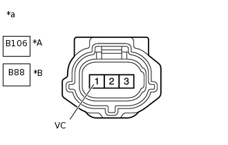
*A
for Manual Transaxle Models
*B
for CVT Models
*a
Front view of wire harness connector
(to Crankshaft Position Sensor)
Disconnect the crankshaft position sensor connector.
Turn the ignition switch to ON.
Measure the voltage according to the value(s) in the table below.
Standard Voltage
Table 1. for Manual Transaxle Models Tester Connection
Condition
Specified Condition
B106-1 (VC) - Body ground
Ignition switch ON
4.5 to 5.5 V
Table 2. for CVT Models Tester Connection
Condition
Specified Condition
B88-1 (VC) - Body ground
Ignition switch ON
4.5 to 5.5 V
Result
Proceed to
OK
NG
NG CHECK HARNESS AND CONNECTOR (CRANKSHAFT POSITION SENSOR - ECM)Click here
-
CHECK HARNESS AND CONNECTOR (CRANKSHAFT POSITION SENSOR - ECM)
Disconnect the crankshaft position sensor connector.
Disconnect the ECM connector.
Measure the resistance according to the value(s) in the table below.
Standard Resistance
Table 3. for Manual Transaxle Models Tester Connection
Condition
Specified Condition
B106-3 (NE+) - B93-114 (NE+)
Always
Below 1 Ω
B106-2 (NE-) - B93-113 (NE-)
Always
Below 1 Ω
B106-3 (NE+) or B93-114 (NE+) - Body ground and other terminals
Always
10 kΩ or higher
B106-2 (NE-) or B93-113 (NE-) - Body ground and other terminals
Always
10 kΩ or higher
Table 4. for CVT Models Tester Connection
Condition
Specified Condition
B88-3 (NE+) - B93-114 (NE+)
Always
Below 1 Ω
B88-2 (NE-) - B93-113 (NE-)
Always
Below 1 Ω
B88-3 (NE+) or B93-114 (NE+) - Body ground and other terminals
Always
10 kΩ or higher
B88-2 (NE-) or B93-113 (NE-) - Body ground and other terminals
Always
10 kΩ or higher
Result
Proceed to
OK
NG
NG REPAIR OR REPLACE HARNESS OR CONNECTOR
CHECK SENSOR INSTALLATION (CRANKSHAFT POSITION SENSOR)
-
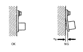
*a
Clearance
Check the crankshaft position sensor installation condition.
OK
Crankshaft position sensor is installed correctly.
Result
Proceed to
OK
NG
-
INSPECT NO. 1 CRANKSHAFT POSITION SENSOR PLATE (TEETH OF SENSOR PLATE)
Inspect the teeth of the No. 1 crankshaft position sensor plate.
OK
No. 1 crankshaft position sensor plate does not have any cranks or deformation.
Result
Proceed to
OK
NG
REPLACE CRANKSHAFT POSITION SENSOR
Replace the crankshaft position sensor.
Result
Proceed to
NEXT
CHECK WHETHER DTC OUTPUT RECURS
Connect the GTS to the DLC3.
Turn the ignition switch to ON.
Turn the GTS on.
Clear the DTCs.
Powertrain > Engine and ECT > Clear DTCs
Turn the ignition switch off and wait for at least 30 seconds.
Start the engine.
Turn the GTS on.
Drive the vehicle in accordance with the driving pattern described in Confirmation Driving Pattern.
Enter the following menus: Powertrain / Engine and ECT / Trouble Codes.
Read the DTCs.
Powertrain > Engine and ECT > Trouble Codes
Result
Result
Proceed to
DTCs are not output
A
DTC P0336 is output
B
A END
CHECK HARNESS AND CONNECTOR (CRANKSHAFT POSITION SENSOR - ECM)
Disconnect the crankshaft position sensor connector.
Disconnect the ECM connector.
Measure the resistance according to the value(s) in the table below.
Standard Resistance
Table 5. for Manual Transaxle Models Tester Connection
Condition
Specified Condition
B106-1 (VC) - B93-81 (VCNE)
Always
Below 1 Ω
B106-1 (VC) or B93-81 (VCNE) - Body ground and other terminals
Always
10 kΩ or higher
Table 6. for CVT Models Tester Connection
Condition
Specified Condition
B88-1 (VC) - B93-81 (VCNE)
Always
Below 1 Ω
B88-1 (VC) or B93-81 (VCNE) - Body ground and other terminals
Always
10 kΩ or higher
Result
Proceed to
OK
NG
NG REPAIR OR REPLACE HARNESS OR CONNECTOR