FRAME WIRE INSTALLATION
PROCEDURE
-
INSTALL FRAME WIRE
CAUTION:
Wear insulated gloves.
-
Install the frame wire with 3 new clamps.
-
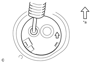
Text in Illustration *a Front of Vehicle Insert the frame wire into the floor panel hole.
Tech Tips
The arrow should be pointing toward the front of the vehicle.
-
Install the 3 nuts.
- Torque:
- 8.4 N*m { 86 kgf*cm, 74 in.*lbf }
-
Install the bolt.
- Torque:
- 8.4 N*m { 86 kgf*cm, 74 in.*lbf }
-
Install the nut and clamp.
- Torque:
- 8.4 N*m { 86 kgf*cm, 74 in.*lbf }
-
Install the nut and 2 clamps.
- Torque:
- 8.4 N*m { 86 kgf*cm, 74 in.*lbf }
-
Install the heater water pipe sub-assembly with the nut.
- Torque:
- 9.8 N*m { 100 kgf*cm, 87 in.*lbf }
-
Connect the 4 clamps.
-
Connect the connector to the engine room junction block assembly.
-
Engage the 3 claws.
-
Connect the 4 wire harness clamps to the floor panel.
-
Connect the clamp to the floor panel to install the wire harness protector.
-
Install the floor carpet with the 2 clips.
-
-
CONNECT HYBRID BATTERY JUNCTION BLOCK ASSEMBLY
CAUTION:
Wear insulated gloves.
-
Install the frame wire on the hybrid battery junction block assembly with the 3 nuts.
- Torque:
- 9.0 N*m { 92 kgf*cm, 80 in.*lbf }
Note
-
Make sure that the ends of the frame wire are not crossed over each other.
-
Be sure to connect the ends of the frame wire to the connect terminals.
-
-
CONNECT CABLE TO POSITIVE AUXILIARY BATTERY TERMINAL
-
Connect the 4 clamps.
-
Install the nut.
- Torque:
- 5.4 N*m { 55 kgf*cm, 48 in.*lbf }
-
Install the terminal cover.
-
-
INSTALL DECK TRIM SIDE PANEL ASSEMBLY RH
Tech Tips
Use the same procedure as for the LH side Click here.
-
INSTALL NO. 1 CUP HOLDER
-
INSTALL FRONT DECK SIDE TRIM COVER RH
Tech Tips
Use the same procedure as for the LH side Click here.
-
INSTALL LUGGAGE HOLD BELT STRIKER ASSEMBLY (for RH Side)
Tech Tips
Use the same procedure as for the LH side Click here.
-
INSTALL NO. 1 DECK TRIM COVER (for RH Side)
Tech Tips
Use the same procedure as for the LH side Click here.
-
CONNECT REAR NO. 2 SEAT OUTER BELT ASSEMBLY RH
-
CONNECT REAR NO. 1 SEAT OUTER BELT ASSEMBLY RH
-
INSTALL BACK DOOR SCUFF PLATE
-
INSTALL REAR NO. 2 SEAT ASSEMBLY
-
INSTALL REAR NO. 1 SEAT ASSEMBLY (for Center)
-
INSTALL REAR NO. 1 SEAT ASSEMBLY (for Side)
-
INSTALL TONNEAU COVER ASSEMBLY (w/ Tonneau Cover)
-
INSTALL FRONT SUSPENSION MEMBER REAR BRACE RH
-
Using a transmission jack, hold the front suspension cross member.
Note
Be sure to position the transmission jack to properly support the front suspension cross member.
-
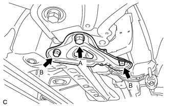
Remove the bolt A
-
Install the front suspension member rear brace RH with the 2 bolts B and bolt A.
- Torque:
- Bolt A
- 137 N*m { 1397 kgf*cm, 101 ft.*lbf }
- Bolt B
- 93 N*m { 948 kgf*cm, 69 ft.*lbf }
-
-
INSTALL FRONT NO. 1 FLOOR HEAT INSULATOR
-
Install the No. 1 front floor heat insulator with the 3 nuts.
- Torque:
- 5.5 N*m { 56 kgf*cm, 49 in.*lbf }
-
-
INSTALL FRONT EXHAUST PIPE ASSEMBLY
-
INSTALL INVERTER WITH CONVERTER ASSEMBLY
-
INSTALL NO. 1 HYBRID BATTERY SHIELD SUB-ASSEMBLY
-
INSTALL CONSOLE BOX ASSEMBLY
-
INSTALL FRONT NO. 2 CONSOLE BOX INSERT
-
INSTALL UPPER CONSOLE PANEL SUB-ASSEMBLY
-
INSTALL CENTER FLOOR CARPET COVER LH
-
INSTALL CENTER FLOOR CARPET COVER RH
-
INSTALL SERVICE PLUG GRIP