IMMOBILISER SYSTEM(w/ Entry and Start System), Diagnostic DTC:B2799
| DTC Code | DTC Name |
|---|---|
| B2799 | Engine Immobiliser System Malfunction |
DESCRIPTION
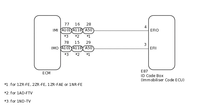
When there is a communication malfunction between the ECM and ID code box (immobiliser code ECU), or when the communication ID codes do not match, the ECM stores this DTC.
DTC No. |
Detection Item |
DTC Detection Condition |
Trouble Area |
Note |
|---|---|---|---|---|
B2799 |
Engine Immobiliser System Malfunction |
Either condition is met (1 trip detection logic*1):
|
|
DTC output confirmation operation (Either condition is met):
|
*1: Only output while a malfunction is present.
*2: for CVT
*3: for Multi-Mode Manual Transaxle
*4: for Manual Transaxle
Vehicle Condition when Malfunction Detected |
Fail-safe Operation when Malfunction Detected |
|---|---|
Engine cannot be started |
- |
DTC No. |
Data List and Active Test |
|---|---|
B2799 |
- |
WIRING DIAGRAM
CAUTION / NOTICE / HINT
When using the GTS with the engine switch off, connect the GTS to the DLC3 and turn a courtesy light switch on and off at intervals of 1.5 seconds or less until communication between the GTS and the vehicle begins. Then select Model Code "KEY REGIST" under manual mode and enter the following menus: Body Electrical / Entry&Start(CAN). While using the GTS, periodically turn a courtesy light switch on and off at intervals of 1.5 seconds or less to maintain communication between the GTS and the vehicle.
When replacing the certification ECU (smart key ECU assembly) or ID code box (immobiliser code ECU) refer to Service Bulletin.
After repair, confirm that no DTCs are output by performing "DTC Output Confirmation Operation."
When DTC B2799 and a certification ECU (smart key ECU assembly) DTC are output simultaneously, first perform troubleshooting for the certification ECU (smart key ECU assembly) DTC.
PROCEDURE
CLEAR DTC
Clear the DTCs.
Powertrain > Engine and ECT > Clear DTCs
Powertrain > Engine and ECT > Clear DTCs
Result
Proceed to
NEXT
CHECK FOR DTC
Start the engine.
Check for DTCs.
Powertrain > Engine and ECT > Trouble Codes
Powertrain > Engine and ECT > Trouble Codes
Tip:Before checking for DTCs, perform the "DTC Output Confirmation Operation" procedure.
OK
B2799 is not output.
Result
Result
Proceed to
OK
A
NG (DTC B2799 is output)
B
NG (Other DTCs are output)
C
INSPECT ECM (TERMINAL IMO)
for 1ZR-FE, 2ZR-FE, 1ZR-FAE or 1NR-FE
Using an oscilloscope, check the waveform.
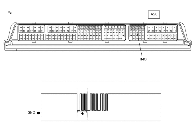
*a
Component with harness connected
(ECM)
*b
Waveform
Table 3. Measurement Condition Item
Content
Tester Connection
A50-29 (IMO) - Body ground
Tool Setting
2 V/DIV., 500 ms./DIV.
Condition
Within 3 seconds of engine start, or within 3 seconds of engine switch turned on (IG) after battery cable disconnected and reconnected
for 1ND-TV
Using an oscilloscope, check the waveform.
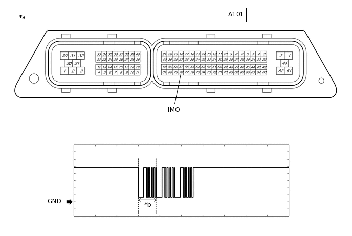
*a
Component with harness connected
(ECM)
*b
Waveform
Table 4. Measurement Condition Item
Content
Tester Connection
A101-78 (IMO) - Body ground
Tool Setting
2 V/DIV., 500 ms./DIV.
Condition
Within 3 seconds of engine start, or within 3 seconds of engine switch turned on (IG) after battery cable disconnected and reconnected
for 1AD-FTV
Using an oscilloscope, check the waveform.
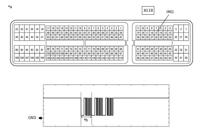
*a
Component with harness connected
(ECM)
*b
Waveform
Table 5. Measurement Condition Item
Content
Tester Connection
A118-15 (IMO) - Body ground
Tool Setting
2 V/DIV., 500 ms./DIV.
Condition
Within 3 seconds of engine start, or within 3 seconds of engine switch turned on (IG) after battery cable disconnected and reconnected
OK
The waveform is similar to that shown in the illustration.
Result
Result
Proceed to
Normal waveform
A
Terminal IMO stuck low (2.4 V or less)
B
Terminal IMO stuck high (12 V) or Abnormal waveform
C
INSPECT ECM (TERMINAL IMI)
for 1ZR-FE, 2ZR-FE, 1ZR-FAE or 1NR-FE
Using an oscilloscope, check the waveform.
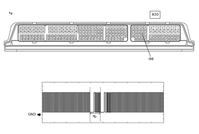
*a
Component with harness connected
(ECM)
*b
Waveform
Table 6. Measurement Condition Item
Content
Tester Connection
A50-28 (IMI) - Body ground
Tool Setting
2 V/DIV., 500 ms./DIV.
Condition
Engine switch on (IG)
for 1ND-TV
Using an oscilloscope, check the waveform.
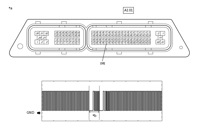
*a
Component with harness connected
(ECM)
*b
Waveform
Table 7. Measurement Condition Item
Content
Tester Connection
A101-77 (IMI) - Body ground
Tool Setting
2 V/DIV., 500 ms./DIV.
Condition
Engine switch on (IG)
for 1AD-FTV
Using an oscilloscope, check the waveform.
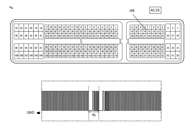
*a
Component with harness connected
(ECM)
*b
Waveform
Table 8. Measurement Condition Item
Content
Tester Connection
A118-16 (IMI) - Body ground
Tool Setting
2 V/DIV., 500 ms./DIV.
Condition
Engine switch on (IG)
OK
The waveform is similar to that shown in the illustration.
Result
Result
Proceed to
OK
A
NG
B
B REPLACE ID CODE BOX (IMMOBILISER CODE ECU)Click here
REGISTER ECU COMMUNICATION ID
Reregister the ECU communication ID.
Tip:Refer to Service Bulletin
Result
Proceed to
NEXT
CHECK WHETHER ENGINE STARTS
Using a registered vehicle key, turn the engine switch on (IG).
Check that the engine starts 5 seconds after the engine switch turned on (IG).
OK
Engine starts normally.
Result
Proceed to
OK
NG
OK END (COMMUNICATION ID REGISTRATION WAS DEFECTIVE)
REPLACE ECM
Temporarily replace the ECM with a new one.
for 1AD-FTV:Click here
for 1ND-TV:Click here
for 1NR-FE:Click here
for 1ZR-FAE:Click here
for 1ZR-FE:Click here
for 2ZR-FE:Click here
Result
Proceed to
NEXT
REGISTER ECU COMMUNICATION ID
Reregister the ECU communication ID.
Tip:Refer to Service Bulletin
Result
Proceed to
NEXT
CHECK WHETHER ENGINE STARTS
Using a registered vehicle key, turn the engine switch on (IG).
Check that the engine starts 5 seconds after the engine switch turned on (IG).
OK
Engine starts normally.
Result
Proceed to
OK
NG
OK END (ECM WAS DEFECTIVE)
NG REPLACE ID CODE BOX (IMMOBILISER CODE ECU)
INSPECT ECM (IMO TERMINAL VOLTAGE)
for 1ZR-FE, 2ZR-FE, 1ZR-FAE or 1NR-FE
Disconnect the A50 ECM connector.
Turn the engine switch on (IG).
-
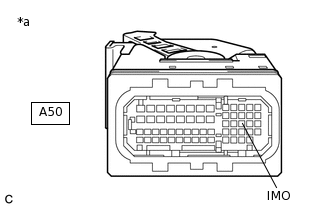
*a
Front view of wire harness connector
(to ECM)
Measure the voltage according to the value(s) in the table below.
Standard Voltage
Tester Connection
Condition
Result
A50-29 (IMO) - Body ground
Engine switch on (IG) using registered key
Terminal IMO stuck low (2.4 V or less)
Terminal IMO stuck high (12 V) or Abnormal waveform
for 1ND-TV
Disconnect the A101 ECM connector.
Turn the engine switch on (IG).
-
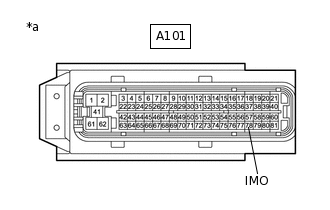
*a
Front view of wire harness connector
(to ECM)
Measure the voltage according to the value(s) in the table below.
Standard Voltage
Tester Connection
Condition
Result
A101-78 (IMO) - Body ground
Engine switch on (IG) using registered key
Terminal IMO stuck low (2.4 V or less)
Terminal IMO stuck high (12 V) or Abnormal waveform
for 1AD-FTV
Disconnect the A118 ECM connector.
Turn the engine switch on (IG).
-
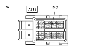
*a
Front view of wire harness connector
(to ECM)
Measure the voltage according to the value(s) in the table below.
Standard Voltage
Tester Connection
Condition
Result
A118-15 (IMO) - Body ground
Engine switch on (IG) using registered key
Terminal IMO stuck low (2.4 V or less)
Terminal IMO stuck high (12 V) or Abnormal waveform
Result
Result
Proceed to
Terminal IMO stuck low (2.4 V or less)
A
Terminal IMO stuck high (12 V) or Abnormal waveform
B
B REPLACE ECMClick here
CHECK HARNESS AND CONNECTOR (ID CODE BOX (IMMOBILISER CODE ECU) - ECM)
for 1ZR-FE, 2ZR-FE, 1ZR-FAE or 1NR-FE
Disconnect the E87 ID code box (immobiliser code ECU) connector.
Disconnect the A50 ECM connector.
Measure the resistance according to the value(s) in the table below.
Standard Resistance
Tester Connection
Condition
Specified Condition
E87-3 (EFII) - A50-29 (IMO)
Always
Below 1 Ω
A50-29 (IMO) - Body ground
Always
10 kΩ or higher
E87-3 (EFII) - Body ground
Always
10 kΩ or higher
E87-4 (EFIO) - A50-28 (IMI)
Always
Below 1 Ω
A50-28 (IMI) - Body ground
Always
10 kΩ or higher
E87-4 (EFIO) - Body ground
Always
10 kΩ or higher
for 1ND-TV
Disconnect the E87 ID code box (immobiliser code ECU) connector.
Disconnect the A101 ECM connector.
Measure the resistance according to the value(s) in the table below.
Standard Resistance
Tester Connection
Condition
Specified Condition
E87-3 (EFII) - A101-78 (IMO)
Always
Below 1 Ω
A101-78 (IMO) - Body ground
Always
10 kΩ or higher
E87-3 (EFII) - Body ground
Always
10 kΩ or higher
E87-4 (EFIO) - A101-77 (IMI)
Always
Below 1 Ω
A101-77 (IMI) - Body ground
Always
10 kΩ or higher
E87-4 (EFIO) - Body ground
Always
10 kΩ or higher
for 1AD-FTV
Disconnect the E87 ID code box (immobiliser code ECU) connector.
Disconnect the A118 ECM connector.
Measure the resistance according to the value(s) in the table below.
Standard Resistance
Tester Connection
Condition
Specified Condition
E87-3 (EFII) - A118-15 (IMO)
Always
Below 1 Ω
A118-15 (IMO) - Body ground
Always
10 kΩ or higher
E87-3 (EFII) - Body ground
Always
10 kΩ or higher
E87-4 (EFIO) - A118-16 (IMI)
Always
Below 1 Ω
A118-16 (IMI) - Body ground
Always
10 kΩ or higher
E87-4 (EFIO) - Body ground
Always
10 kΩ or higher
Result
Proceed to
OK
NG
NG REPAIR OR REPLACE HARNESS OR CONNECTOR
REPLACE ID CODE BOX (IMMOBILISER CODE ECU)
Replace the ID code box (immobiliser code ECU) with a new one.
Tip:Refer to Service Bulletin.
Note:Recognition code registration is necessary when replacing the ID code box (immobiliser code ECU).
Refer to Service Bulletin.
Result
Proceed to
NEXT
CHECK WHETHER ENGINE STARTS
Using a registered vehicle key, turn the engine switch on (IG).
Check that the engine starts 5 seconds after the engine switch was turn on (IG).
OK
Engine starts normally.
Result
Result
Proceed to
OK
A
NG (for 1AD-FTV)
B
NG (for 1ND-TV)
C
NG (for 1NR-FE)
D
NG (for 1ZR-FAE)
E
NG (for 1ZR-FE)
F
NG (for 2ZR-FE)
G
A END (ID CODE BOX (IMMOBILISER CODE ECU) WAS DEFECTIVE)