SLIDING ROOF HOUSING INSTALLATION
PROCEDURE
INSTALL SLIDING ROOF HOUSING SUB-ASSEMBLY
w/o Center Bracket:
Temporarily install the sliding roof housing sub-assembly with the 8 nuts.
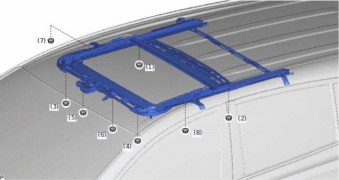
Tighten the nuts in the order indicated in the illustration.
5.5 N*m
56 kgf*cm
49 in.*lbf
Temporarily install the 4 bolts on the vehicle interior side.
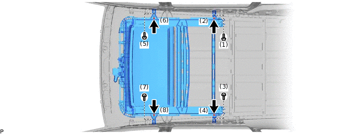
Tighten the bolts in the order indicated in the illustration.
8.0 N*m
82 kgf*cm
71 in.*lbf
w/ Center Bracket:
Temporarily install the sliding roof housing sub-assembly with the 8 nuts.
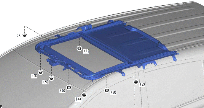
Tighten the nuts in the order indicated in the illustration.
5.5 N*m
56 kgf*cm
49 in.*lbf
Temporarily install the 8 bolts on the vehicle interior side.
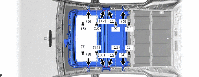
Tighten the bolts in the order indicated in the illustration.
8.0 N*m
82 kgf*cm
71 in.*lbf
-
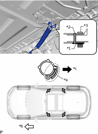
*1
Marking A
*2
Marking B
*3
Clamp
*a
Lock Area
*b
Front Side
*c
Out Side
Insert the sliding roof drain hose.
Tip:The hose should be inserted to the base of the drain pipe.
Make sure that marking A on the drain hose is facing toward the bottom of the vehicle.
Attach the claw to connect the sliding roof drain hose.
Note:Make sure that the lock area of the clamp is facing toward the outside of the vehicle when installing the clamp.
Install the clamp on the side of marking B that is closest to the sliding roof housing.
Tip:Use the same procedure for the other 3 sliding roof drain hoses.
INSTALL REAR SIDE RAIL SPACER LH
INSTALL REAR SIDE RAIL SPACER RH
Tip:Use the same procedure as for the LH side.
INSTALL CURTAIN SHIELD AIRBAG ASSEMBLY LH
INSTALL CURTAIN SHIELD AIRBAG ASSEMBLY RH
Tip:Use the same procedure as for the LH side.
INSTALL SLIDING ROOF WEATHERSTRIP
Install the sliding roof weatherstrip as follows:
Align the alignment mark (blue) on the weatherstrip with the middle marks at the corners of the sliding roof panel sub-assembly as shown in the illustration.
Position the centers of the 2 joints of the sliding roof weatherstrip as shown in the illustration and install the weatherstrip.
Install the lip of the weatherstrip firmly.
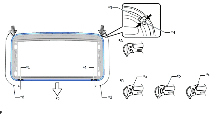
*A
Normal
*B
Abnormal
*1
Center of Joint
*2
Rear
*3
Alignment Mark (Blue)
*4
Middle Mark
*a
Pinched
*b
Exposed
*c
Gap (raised, wavy, etc.)
*d
46.6 cm (1.53 ft.)
INSTALL SLIDING ROOF GLASS SUB-ASSEMBLY
Using a T25 "TORX" socket wrench, temporarily install the sliding roof glass sub-assembly with the 4 screws.
Perform a level check.
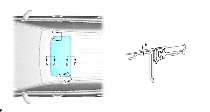
Check the difference in level for "a" between the roof panel and the upper surface of the weatherstrip when the sliding roof glass is fully closed.
Standard
Area
Measurement
A - A
0 + 1.0 mm (0 + 0.0394 in.)
0 - 2.0 mm (0 - 0.0787 in.)
B - B
0 + 2.0 mm (0 + 0.0787 in.)
0 - 1.0 mm (0 - 0.0394 in.)
C - C
0 + 1.5 mm (0 + 0.0591 in.)
0 - 1.5 mm (0 - 0.0591 in.)
D - D
0 + 1.5 mm (0 + 0.0591 in.)
0 - 1.0 mm (0 - 0.0394 in.)
Tip:"+" represents the condition that the glass is above the panel level. "-" represents the condition that the glass is below the panel level.
-
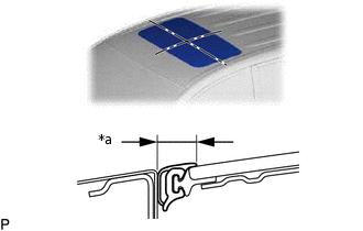
*a
Even
Perform a gap check.
Check the gap between the roof panel and roof glass.
Note:The gap must be even all around.
After adjusting the sliding roof glass, using a T25 "TORX" socket wrench, install the sliding roof glass sub-assembly with the 4 screws.
4.0 N*m
41 kgf*cm
35 in.*lbf
CHECK FOR WATER LEAK
After adjusting the sliding roof glass sub-assembly, check for water leaks.
If there are any leaks, readjust the sliding roof glass sub-assembly.
INSTALL SLIDING ROOF SIDE GARNISH LH
Attach the 2 claws and install a new sliding roof side garnish LH.
INSTALL SLIDING ROOF SIDE GARNISH RH
Tip:Use the same procedure as for the LH side.
INSTALL ROOF HEADLINING ASSEMBLY
RESET SLIDING ROOF DRIVE GEAR SUB-ASSEMBLY
CHECK SLIDING ROOF SYSTEM
INSPECT FOR WATER LEAK
After adjusting the sliding roof glass sub-assembly, inspect for water leaks.
If there are any leaks, readjust the sliding roof glass sub-assembly.