BLIND SPOT MONITOR SYSTEM
-
FUNCTION OF MAIN COMPONENTS
-
The blind spot monitor system has the following functions:
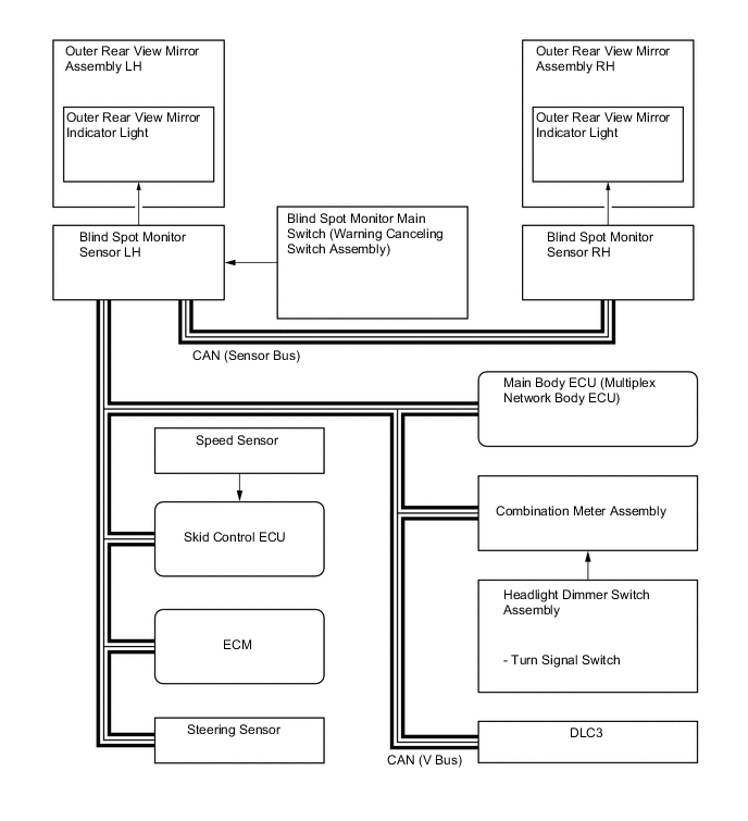
Function Outline Blind Spot Monitor Sensors LH and RH
-
Output millimeter waves from the blind spot monitor sensor to the blind spot sensor detection area, uses the reflected millimeter waves for detecting the presence of a vehicle, the vehicle-to-vehicle distance and the relative speed, and then transmits this information to the built-in signal processing circuit.
-
The signal processing circuit determines if a vehicle is present, and illuminates or blinks the outer rear view mirror indicator accordingly.
-
Dim the outer rear view mirror indicator light on the outer rear view mirror assembly.
Blind Spot Monitor Main Switch (Warning Canceling Switch Assembly) Pressing the blind spot monitor main switch turns the blind spot monitor system on or off. Outer Rear View Mirror Assembly
-
Outer Rear View Mirror Indicator Light
-
Illuminates when a vehicle is detected in the detection area (blind spot monitor function).
-
Blinks when the turn signal switch is operated while a vehicle is detected in the detection area (blind spot monitor function).
-
Blinks when another vehicle is detected in the alert area while the vehicle is backing up (RCTA function).
Headlight Dimmer Switch Assembly
-
Turn Signal Switch
Transmits the turn signal switch signal to the blind spot monitor sensors LH and RH. Combination Meter Assembly Blind Spot Monitor Indicator Illuminates the blind spot monitor indicator when the blind spot monitor system malfunctions and when the system cannot be used temporarily to inform the driver. Steering Sensor Transmits the steering angle signal to the blind spot monitor sensors LH and RH. Skid Control ECU Transmits the vehicle speed signal to the blind spot monitor sensors LH and RH. Main Body ECU (Multiplex Network Body ECU)
-
Transmits the destination signal to the blind spot monitor sensors LH and RH.
-
Transmits the taillight signal to the blind spot monitor sensors LH and RH.
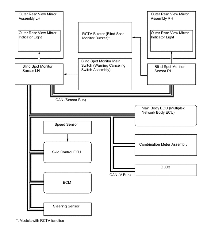
ECM Transmits the reverse signal to the blind spot monitor sensors LH and RH. RCTA Buzzer (Blind Spot Monitor Buzzer)* Sounds when a vehicle is detected in the alert area while backing up.
-
*: Models with RCTA function
-
-
-
SYSTEM CONTROL
-
Operating Condition (Blind Spot Monitor Function)
-
The blind spot monitor function operates when both of the following conditions are met:
-
The blind spot monitor main switch is on.
-
The vehicle speed is greater than approximately 16 km/h (10 mph).
-
-
The blind spot monitor function can detect vehicles in its detection areas.
-
The detection areas formed by the blind spot monitor sensors LH and RH are as shown below:
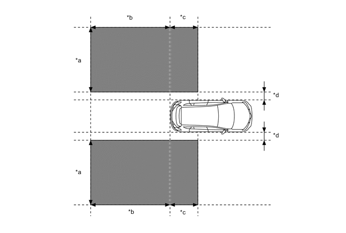
*a 3.5 m (11.5 ft.) *b 3.0 m (9.8 ft.) *c 1.0 m (3.3 ft.) *d 0.5 m (1.6 ft.) 
Detection Area - - -
When this vehicle is overtaken by another vehicle in the adjacent lane.
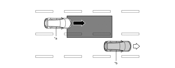
*a Other Vehicle *b This Vehicle 
Vehicle Speed (Fast) 
Vehicle Speed (Slow) Detection Area - - -
When another vehicle enters the detection area of this vehicle due to a lane change.
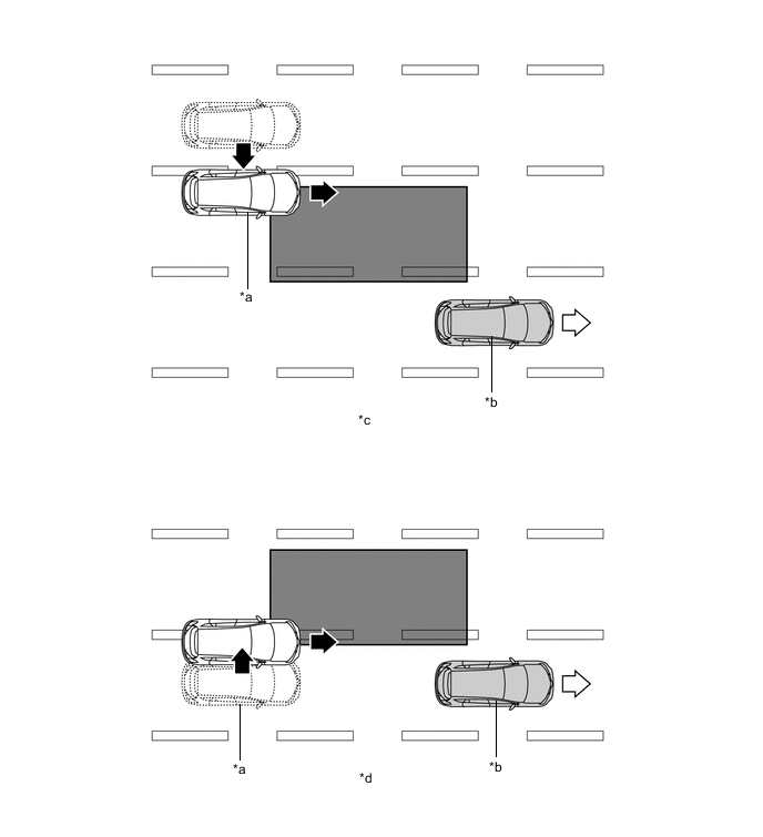
*a Other Vehicle *b This Vehicle *c Other vehicle enters the detection area during lane change (merge in) (Type 1). *d Other vehicle enters the detection area during lane change (merge in) (Type 2). Motion Direction of Other Vehicle Motion Direction of This Vehicle Detection Area - -
-
-
-
Operating Condition (RCTA Function)
-
The RCTA function can detect vehicles in its detection areas.
-
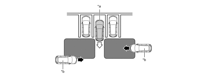
The system continuously measures the relative speed of an approaching vehicle and its distance. If it is determined that the approaching vehicle will cross in the path of this vehicle, the Estimated Crossing Time (ECT) is calculated. When the ECT is 2.5 seconds or less, the system alerts the driver by flashing the outer rear view mirror indicator lights and sounding the RCTA buzzer.
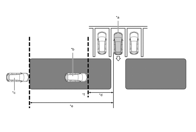
*a This Vehicle *b Target Vehicle (Approximately 8 km/h (5 mph)) *c Target Vehicle (Approximately 28 km/h (18 mph)) *d Approximately 5.5 m (18.0 ft.) *e Approximately 20 m (65.6 ft.) *f Target Detection Line Alert Area - - -
Normal Parking
*a This Vehicle *b Target Vehicle Alert Area - - -
Angle Parking
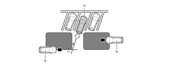
*a This Vehicle *b Target Vehicle *c Approximately 55 to 140 degree - - Alert Area - -
-
-
-
-
FUNCTION
-
Blind Spot Monitor Function
-
According to operation conditions, the blind spot monitor function promotes safety confirmation by using the outer rear view mirror indicator light to inform the driver that another vehicle has entered the blind spot monitor sensor detection area of this vehicle.
-
The outer rear view mirror indicator light informs the driver that a vehicle is present in the blind spot detection area by illuminating when the turn light switch is not operated, and by flashing when a vehicle is present and the turn light switch is operated.
-
-
RCTA Function
-
According to operation conditions, the RCTA function promotes safety confirmation by using the outer rear view mirror indicator lights and RCTA buzzer to inform the driver that another vehicle has entered the blind spot monitor sensor alert area of this vehicle.
-
When this vehicle is reversing, if a vehicle enters the alert area of the blind sport monitor sensors and it is determined the vehicle will cross in the path of this vehicle, the system alerts the driver by flashing the outer rear view mirror indicator lights and sounding the RCTA buzzer.
-
-
-
DIAGNOSIS
-
The blind spot monitor system is equipped with a diagnosis function that can illuminate the blind spot monitor indicator on the combination meter assembly. For details, refer to the Repair Manual.
-