DYNAMIC RADAR CRUISE CONTROL SYSTEM, Diagnostic DTC:P057113
| DTC Code | DTC Name |
|---|---|
| P057113 | Brake Switch "A" Circuit Open |
DESCRIPTION
When the brakes are applied by the dynamic radar cruise control system, the skid control ECU (brake actuator assembly) operates the No. 3 semiconductor power integration ECU to illuminate the stop lights.
If the ECM receives a No. 3 semiconductor power integration ECU malfunction signal from the skid control ECU (brake actuator assembly), DTC P057113 is stored.
| DTC No. | Detection Item | DTC Detection Condition | Trouble Area |
|---|---|---|---|
| P057113 | Brake Switch "A" Circuit Open |
w/o Full-speed range following function:
w/ Full-speed range following function: |
|
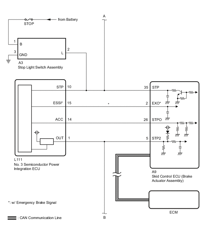
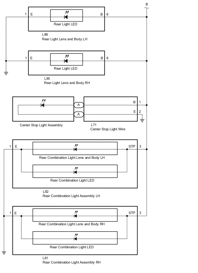
WIRING DIAGRAM
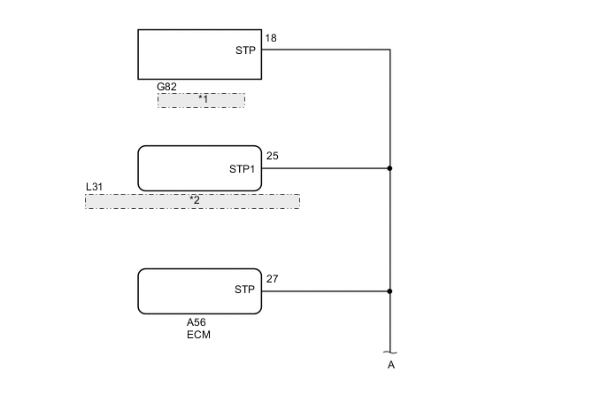
| *1 | Shift Control ECU |
| *2 | Certification ECU (Smart Key ECU Assembly) |
CAUTION / NOTICE / HINT
Note
-
Before replacing the certification ECU (smart key ECU assembly), refer to the Service Bulletin.
-
The vehicle is equipped with a sub-battery. Therefore, ensure there is no power being supplied to the vehicle when disconnecting or reconnecting the connector of the shift control ECU and when removing or installing the shift control ECU.
PROCEDURE
-
CHECK FOR DTCs (POWER INTEGRATION SYSTEM)
-
Check for DTCs.
Body Electrical > Power Integration No.3 > Trouble CodesTech Tips
If there is a malfunction in the No. 3 semiconductor integration ECU, integration relay system DTCs may also have been detected. Check the integration relay system first.
Result Result Proceed to Power integration system DTCs are not output A Power integration system DTCs are output B
B 
GO TO POWER INTEGRATION SYSTEM Click here
A 
-
-
READ VALUE USING GTS (STOP LIGHT INPUT SIGNAL, STOP LIGHT OUTPUT SIGNAL AND STATUS OF STOP LIGHT FUSE)
-
Using the GTS, check the Data List "Stop Light Input Signal", "Stop Light Output Signal" and "Status of Stop Light Fuse" with the brake pedal operated.
Body Electrical > Power Integration No.3 > Data ListTester Display Measurement Item Range Normal Condition Diagnostic Note Stop Light Input Signal Stop light switch assembly input condition ON or OFF OFF: Brake pedal released
ON: Brake pedal depressed
- Stop Light Output Signal Stop light output condition ON or OFF OFF:
Stop light is off
ON:
Stop light is on
Stop lights blink during emergency brake signal control Status of Stop Light Fuse Stop light fuse condition Disconnect or Connect Disconnect: Fuse shut off
Connect: Fuse not shut off
-
Body Electrical > Power Integration No.3 > Data ListTester Display Stop Light Input Signal Stop Light Output Signal Status of Stop Light Fuse Standard Brake pedal operation Data List Display Condition Stop Light Input Signal Stop Light Output Signal Status of Stop Light Fuse Brake pedal depressed ON ON Connect Result Brake pedal operation Data List Display Condition Result Stop Light Input Signal Stop Light Output Signal Status of Stop Light Fuse Brake pedal depressed ON ON Connect A ON OFF Connect B ON OFF Disconnect C OFF OFF Connect D
B
REPLACE NO.3 SEMICONDUCTOR POWER INTEGRATION ECU Click here
C 
READ VALUE USING GTS (STOP LIGHT OUTPUT SIGNAL AND STATUS OF STOP LIGHT FUSE) Click here
D
CHECK HARNESS AND CONNECTOR (NO. 3 SEMICONDUCTOR POWER INTEGRATION ECU - SKID CONTROL ECU (BRAKE ACTUATOR ASSEMBLY)) Click here
A
-
-
CHECK TERMINAL VOLTAGE (STP, STPO AND STP2 TERMINAL)
-
Disconnect the A9 skid control ECU (brake actuator assembly) connectors.
-
Measure the voltage according to the value(s) in the table below.
Standard Voltage Tester Connection Condition Specified Condition A9-35 (STP) - Body ground Brake pedal depressed 8 to 14 V Brake pedal released Below 1.5 V A9-26 (STPO) - Body ground Engine switch off 8 to 14 V A9-5 (STP2) - Body ground Brake pedal depressed 8 to 14 V Brake pedal released Below 1.5 V -
Connect the A9 skid control ECU (brake actuator assembly) connectors.
Result Result Proceed to All terminal voltage is normal A Only STP terminal voltage abnormal B Only STPO terminal voltage abnormal C Only STP2 terminal voltage abnormal D STPO terminal and STP2 terminal voltage abnormal E
B
REPAIR OR REPLACE HARNESS OR CONNECTOR
C
CHECK HARNESS AND CONNECTOR (SKID CONTROL ECU (BRAKE ACTUATOR ASSEMBLY) - NO. 3 SEMICONDUCTOR POWER INTEGRATION ECU) Click here
D
CHECK HARNESS AND CONNECTOR (SKID CONTROL ECU (BRAKE ACTUATOR ASSEMBLY) - NO. 3 SEMICONDUCTOR POWER INTEGRATION ECU) Click here
E
CHECK HARNESS AND CONNECTOR (SKID CONTROL ECU (BRAKE ACTUATOR ASSEMBLY) - NO. 3 SEMICONDUCTOR POWER INTEGRATION ECU) Click here
A
-
-
PERFORM ACTIVE TEST USING GTS (STOP LIGHT RELAY)
-
Enter the following menus: Chassis / ABS/VSC/TRC / Active Test.
-
Perform "Active Test" according to the display on the GTS.
Chassis > ABS/VSC/TRC > Active TestTester Display Measurement Item Control Range Diagnostic Note Stop Light Relay No. 3 semiconductor power integration ECU ECU (Stop light output) ON/OFF Stop lights come on
Chassis > ABS/VSC/TRC > Active TestTester Display Stop Light Relay OK Stop light turns ON/OFF in response to the GTS operation Result Proceed to OK NG
NG
INSPECT SKID CONTROL ECU (BRAKE ACTUATOR ASSEMBLY) Click here
OK
-
-
CHECK FOR DTC (RADAR CRUISE 1)
-
Clear the DTCs.
Powertrain > Cruise Control > Clear DTCs -
Enter the following menus: Chassis / ABS/VSC/TRC / Active Test.
-
Perform "Active Test" according to the display on the GTS.
Chassis > ABS/VSC/TRC > Active TestTester Display Measurement Item Control Range Diagnostic Note Stop Light Relay No. 3 semiconductor power integration ECU ECU (Stop light output) ON/OFF Stop lights come on
Chassis > ABS/VSC/TRC > Active TestTester Display Stop Light Relay -
Check for DTCs.
Powertrain > Cruise Control > Trouble CodesResult Result Proceed to DTC P057113 is not output A DTC P057113 is output B
A
USE SIMULATION METHOD TO CHECK Click here
B
REPLACE SKID CONTROL ECU (BRAKE ACTUATOR ASSEMBLY) for LHD: Click here
REPLACE SKID CONTROL ECU (BRAKE ACTUATOR ASSEMBLY) for RHD: Click here -
-
INSPECT SKID CONTROL ECU (BRAKE ACTUATOR ASSEMBLY)
-
Enter the following menus: Chassis / ABS/VSC/TRC / Active Test.
-
Perform "Active Test" according to the display on the GTS.
Chassis > ABS/VSC/TRC > Active TestTester Display Measurement Item Control Range Diagnostic Note Stop Light Relay No. 3 semiconductor power integration ECU ECU (Stop light output) ON / OFF Stop lights come on
Chassis > ABS/VSC/TRC > Active TestTester Display Stop Light Relay -
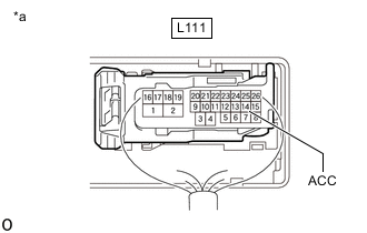
*a Component with harness connected
(No. 3 Semiconductor Power Integration ECU)
Measure the voltage according to the value(s) in the table below.
Standard Voltage Tester Connection Condition Specified Condition L111-14 (ACC) - Body ground Active test is ON Below 1.5 V Result Proceed to OK NG
OK
REPLACE NO.3 SEMICONDUCTOR POWER INTEGRATION ECU Click here
NG
REPLACE SKID CONTROL ECU (BRAKE ACTUATOR ASSEMBLY) for LHD: Click here
REPLACE SKID CONTROL ECU (BRAKE ACTUATOR ASSEMBLY) for RHD: Click here -
-
CHECK HARNESS AND CONNECTOR (SKID CONTROL ECU (BRAKE ACTUATOR ASSEMBLY) - NO. 3 SEMICONDUCTOR POWER INTEGRATION ECU)
-
Disconnect the A9 skid control ECU (brake actuator assembly) connector.
-
Disconnect the L111 No. 3 semiconductor power integration ECU connector.
-
Measure the resistance according to the value(s) in the table below.
Standard Resistance Tester Connection Condition Specified Condition A9-26 (STPO) - L111-14 (ACC) Always Below 1 Ω -
Connect the L111 No. 3 semiconductor power integration ECU connector.
-
Connect the A9 skid control ECU (brake actuator assembly) connector.
Result Proceed to OK NG
OK
REPLACE NO.3 SEMICONDUCTOR POWER INTEGRATION ECU Click here
NG
REPAIR OR REPLACE HARNESS OR CONNECTOR
-
-
CHECK HARNESS AND CONNECTOR (SKID CONTROL ECU (BRAKE ACTUATOR ASSEMBLY) - NO. 3 SEMICONDUCTOR POWER INTEGRATION ECU)
-
Disconnect the L111 No. 3 semiconductor power integration ECU connector.
-
Disconnect the A9 skid control ECU (brake actuator assembly) connector.
-
Measure the resistance according to the value(s) in the table below.
Standard Resistance Tester Connection Condition Specified Condition L111-1 (OUT) - A9-5 (STP2) Always Below 1 Ω -
Connect the A9 skid control ECU (brake actuator assembly) connector.
-
Connect the L111 No. 3 semiconductor power integration ECU connector.
Result Proceed to OK NG
OK
REPLACE NO.3 SEMICONDUCTOR POWER INTEGRATION ECU Click here
NG
REPAIR OR REPLACE HARNESS OR CONNECTOR
-
-
CHECK HARNESS AND CONNECTOR (SKID CONTROL ECU (BRAKE ACTUATOR ASSEMBLY) - NO. 3 SEMICONDUCTOR POWER INTEGRATION ECU)
-
Disconnect the A9 skid control ECU (brake actuator assembly) connector.
-
Disconnect the L111 No. 3 semiconductor power integration ECU connector.
-
Measure the resistance according to the value(s) in the table below.
Standard Resistance Tester Connection Condition Specified Condition A9-26 (STPO) or L111-14 (ACC) - Body ground Always 10 kΩ or higher -
Connect the L111 No. 3 semiconductor power integration ECU connector.
-
Connect the A9 skid control ECU (brake actuator assembly) connector.
Result Proceed to OK NG
OK
REPLACE NO.3 SEMICONDUCTOR POWER INTEGRATION ECU Click here
NG
REPAIR OR REPLACE HARNESS OR CONNECTOR
-
-
READ VALUE USING GTS (STOP LIGHT OUTPUT SIGNAL AND STATUS OF STOP LIGHT FUSE)
-
Disconnect the L82 rear combination light assembly LH connector.
-
Using the GTS, check the Data List "Stop Light Output Signal" and "Status of Stop Light Fuse" with the brake pedal operated.
Body Electrical > Power Integration No.3 > Data ListTester Display Measurement Item Range Normal Condition Diagnostic Note Stop Light Output Signal Stop light output condition ON or OFF OFF:
Stop light is off
ON:
Stop light is on
Stop lights blink during emergency brake signal control Status of Stop Light Fuse Stop light fuse condition Disconnect or Connect Disconnect: Fuse shut off
Connect: Fuse not shut off
-
Body Electrical > Power Integration No.3 > Data ListTester Display Stop Light Output Signal Status of Stop Light Fuse Standard Brake pedal operation Data List Display Condition Stop Light Output Signal Status of Stop Light Fuse Brake pedal depressed ON Connect -
Connect the L82 rear combination light assembly LH connector.
Result Brake pedal operation Data List Display Condition Result Stop Light Output Signal Status of Stop Light Fuse Brake pedal depressed ON Connect A OFF Disconnect B
B
READ VALUE USING GTS (STOP LIGHT OUTPUT SIGNAL AND STATUS OF STOP LIGHT FUSE) Click here
A
-
-
READ VALUE USING GTS (STOP LIGHT OUTPUT SIGNAL AND STATUS OF STOP LIGHT FUSE)
-
Disconnect the rear combination light LED (rear combination light lens and body LH side) connector.
Tech Tips
-
Connect the L82 rear combination light assembly LH connector.
-
Using the GTS, check the Data List "Stop Light Output Signal" and "Status of Stop Light Fuse" with the brake pedal operated.
Body Electrical > Power Integration No.3 > Data ListTester Display Measurement Item Range Normal Condition Diagnostic Note Stop Light Output Signal Stop light output condition ON or OFF OFF:
Stop light is off
ON:
Stop light is on
Stop lights blink during emergency brake signal control Status of Stop Light Fuse Stop light fuse condition Disconnect or Connect Disconnect: Fuse shut off
Connect: Fuse not shut off
-
Body Electrical > Power Integration No.3 > Data ListTester Display Stop Light Output Signal Status of Stop Light Fuse Standard Brake pedal operation Data List Display Condition Stop Light Output Signal Status of Stop Light Fuse Brake pedal depressed ON Connect -
Connect the rear combination light LED (rear combination light lens and body LH side) connector.
Result Brake pedal operation Data List Display Condition Result Stop Light Output Signal Status of Stop Light Fuse Brake pedal depressed ON Connect A OFF Disconnect B
A
REPLACE REAR COMBINATION LIGHT LED Click here
B
REPLACE REAR COMBINATION LIGHT LENS AND BODY LH Click here
-
-
READ VALUE USING GTS (STOP LIGHT OUTPUT SIGNAL AND STATUS OF STOP LIGHT FUSE)
-
Disconnect the L81 rear combination light assembly RH connector.
-
Using the GTS, check the Data List "Stop Light Output Signal" and "Status of Stop Light Fuse" with the brake pedal operated.
Body Electrical > Power Integration No.3 > Data ListTester Display Measurement Item Range Normal Condition Diagnostic Note Stop Light Output Signal Stop light output condition ON or OFF OFF:
Stop light is off
ON:
Stop light is on
Stop lights blink during emergency brake signal control Status of Stop Light Fuse Stop light fuse condition Disconnect or Connect Disconnect: Fuse shut off
Connect: Fuse not shut off
-
Body Electrical > Power Integration No.3 > Data ListTester Display Stop Light Output Signal Status of Stop Light Fuse Standard Brake pedal operation Data List Display Condition Stop Light Output Signal Status of Stop Light Fuse Brake pedal depressed ON Connect -
Connect the L81 rear combination light assembly RH connector.
Result Brake pedal operation Data List Display Condition Result Stop Light Output Signal Status of Stop Light Fuse Brake pedal depressed ON Connect A OFF Disconnect B
B
READ VALUE USING GTS (STOP LIGHT OUTPUT SIGNAL AND STATUS OF STOP LIGHT FUSE) Click here
A
-
-
READ VALUE USING GTS (STOP LIGHT OUTPUT SIGNAL AND STATUS OF STOP LIGHT FUSE)
-
Disconnect the rear combination light LED (rear combination light lens and body RH side) connector.
Tech Tips
-
Connect the L81 rear combination light assembly RH connector.
-
Using the GTS, check the Data List "Stop Light Output Signal" and "Status of Stop Light Fuse" with the brake pedal operated.
Body Electrical > Power Integration No.3 > Data ListTester Display Measurement Item Range Normal Condition Diagnostic Note Stop Light Output Signal Stop light output condition ON or OFF OFF:
Stop light is off
ON:
Stop light is on
Stop lights blink during emergency brake signal control Status of Stop Light Fuse Stop light fuse condition Disconnect or Connect Disconnect: Fuse shut off
Connect: Fuse not shut off
-
Body Electrical > Power Integration No.3 > Data ListTester Display Stop Light Output Signal Status of Stop Light Fuse Standard Brake pedal operation Data List Display Condition Stop Light Output Signal Status of Stop Light Fuse Brake pedal depressed ON Connect -
Connect the rear combination light LED (rear combination light lens and body RH side) connector.
Result Brake pedal operation Data List Display Condition Result Stop Light Output Signal Status of Stop Light Fuse Brake pedal depressed ON Connect A OFF Disconnect B
A
REPLACE REAR COMBINATION LIGHT LED Click here
B
REPLACE REAR COMBINATION LIGHT LENS AND BODY RH Click here
-
-
READ VALUE USING GTS (STOP LIGHT OUTPUT SIGNAL AND STATUS OF STOP LIGHT FUSE)
-
Disconnect the L86 rear light lens and body LH connector.
-
Using the GTS, check the Data List "Stop Light Output Signal" and "Status of Stop Light Fuse" with the brake pedal operated.
Body Electrical > Power Integration No.3 > Data ListTester Display Measurement Item Range Normal Condition Diagnostic Note Stop Light Output Signal Stop light output condition ON or OFF OFF:
Stop light is off
ON:
Stop light is on
Stop lights blink during emergency brake signal control Status of Stop Light Fuse Stop light fuse condition Disconnect or Connect Disconnect: Fuse shut off
Connect: Fuse not shut off
-
Body Electrical > Power Integration No.3 > Data ListTester Display Stop Light Output Signal Status of Stop Light Fuse Standard Brake pedal operation Data List Display Condition Stop Light Output Signal Status of Stop Light Fuse Brake pedal depressed ON Connect -
Connect the L86 rear light lens and body LH connector.
Result Brake pedal operation Data List Display Condition Result Stop Light Output Signal Status of Stop Light Fuse Brake pedal depressed ON Connect A OFF Disconnect B
B
READ VALUE USING GTS (STOP LIGHT OUTPUT SIGNAL AND STATUS OF STOP LIGHT FUSE) Click here
A
-
-
READ VALUE USING GTS (STOP LIGHT OUTPUT SIGNAL AND STATUS OF STOP LIGHT FUSE)
-
Disconnect the rear light LED (rear light lens and body LH side) connector.
Tech Tips
-
Connect the L86 rear light lens and body LH connector.
-
Using the GTS, check the Data List "Stop Light Output Signal" and "Status of Stop Light Fuse" with the brake pedal operated.
Body Electrical > Power Integration No.3 > Data ListTester Display Measurement Item Range Normal Condition Diagnostic Note Stop Light Output Signal Stop light output condition ON or OFF OFF:
Stop light is off
ON:
Stop light is on
Stop lights blink during emergency brake signal control Status of Stop Light Fuse Stop light fuse condition Disconnect or Connect Disconnect: Fuse shut off
Connect: Fuse not shut off
-
Body Electrical > Power Integration No.3 > Data ListTester Display Stop Light Output Signal Status of Stop Light Fuse Standard Brake pedal operation Data List Display Condition Stop Light Output Signal Status of Stop Light Fuse Brake pedal depressed ON Connect -
Connect the rear light LED (rear light lens and body LH side) connector.
Result Brake pedal operation Data List Display Condition Result Stop Light Output Signal Status of Stop Light Fuse Brake pedal depressed ON Connect A OFF Disconnect B
A
REPLACE REAR LIGHT LED Click here
B
REPLACE REAR LIGHT LENS AND BODY LH Click here
-
-
READ VALUE USING GTS (STOP LIGHT OUTPUT SIGNAL AND STATUS OF STOP LIGHT FUSE)
-
Disconnect the L90 rear light lens and body RH connector.
-
Using the GTS, check the Data List "Stop Light Output Signal" and "Status of Stop Light Fuse" with the brake pedal operated.
Body Electrical > Power Integration No.3 > Data ListTester Display Measurement Item Range Normal Condition Diagnostic Note Stop Light Output Signal Stop light output condition ON or OFF OFF:
Stop light is off
ON:
Stop light is on
Stop lights blink during emergency brake signal control Status of Stop Light Fuse Stop light fuse condition Disconnect or Connect Disconnect: Fuse shut off
Connect: Fuse not shut off
-
Body Electrical > Power Integration No.3 > Data ListTester Display Stop Light Output Signal Status of Stop Light Fuse Standard Brake pedal operation Data List Display Condition Stop Light Output Signal Status of Stop Light Fuse Brake pedal depressed ON Connect -
Connect the L90 rear light lens and body RH connector.
Result Brake pedal operation Data List Display Condition Result Stop Light Output Signal Status of Stop Light Fuse Brake pedal depressed ON Connect A OFF Disconnect B
B
READ VALUE USING GTS (STOP LIGHT OUTPUT SIGNAL AND STATUS OF STOP LIGHT FUSE) Click here
A
-
-
READ VALUE USING GTS (STOP LIGHT OUTPUT SIGNAL AND STATUS OF STOP LIGHT FUSE)
-
Disconnect the rear light LED (rear light lens and body RH side) connector.
Tech Tips
-
Connect the L90 rear light lens and body RH connector.
-
Using the GTS, check the Data List "Stop Light Output Signal" and "Status of Stop Light Fuse" with the brake pedal operated.
Body Electrical > Power Integration No.3 > Data ListTester Display Measurement Item Range Normal Condition Diagnostic Note Stop Light Output Signal Stop light output condition ON or OFF OFF:
Stop light is off
ON:
Stop light is on
Stop lights blink during emergency brake signal control Status of Stop Light Fuse Stop light fuse condition Disconnect or Connect Disconnect: Fuse shut off
Connect: Fuse not shut off
-
Body Electrical > Power Integration No.3 > Data ListTester Display Stop Light Output Signal Status of Stop Light Fuse Standard Brake pedal operation Data List Display Condition Stop Light Output Signal Status of Stop Light Fuse Brake pedal depressed ON Connect -
Connect the rear light LED (rear light lens and body RH side) connector.
Result Brake pedal operation Data List Display Condition Result Stop Light Output Signal Status of Stop Light Fuse Brake pedal depressed ON Connect A OFF Disconnect B
A
REPLACE REAR LIGHT LED Click here
B
REPLACE REAR LIGHT LENS AND BODY RH Click here
-
-
READ VALUE USING GTS (STOP LIGHT OUTPUT SIGNAL AND STATUS OF STOP LIGHT FUSE)
-
Disconnect the A center stop light assembly connector.
-
Using the GTS, check the Data List "Stop Light Output Signal" and "Status of Stop Light Fuse" with the brake pedal operated.
Body Electrical > Power Integration No.3 > Data ListTester Display Measurement Item Range Normal Condition Diagnostic Note Stop Light Output Signal Stop light output condition ON or OFF OFF:
Stop light is off
ON:
Stop light is on
Stop lights blink during emergency brake signal control Status of Stop Light Fuse Stop light fuse condition Disconnect or Connect Disconnect: Fuse shut off
Connect: Fuse not shut off
-
Body Electrical > Power Integration No.3 > Data ListTester Display Stop Light Output Signal Status of Stop Light Fuse Standard Brake pedal operation Data List Display Condition Stop Light Output Signal Status of Stop Light Fuse Brake pedal depressed ON Connect -
Connect the A center stop light assembly connector.
Result Brake pedal operation Data List Display Condition Result Stop Light Output Signal Status of Stop Light Fuse Brake pedal depressed ON Connect A OFF Disconnect B
A
REPLACE CENTER STOP LIGHT ASSEMBLY Click here
B
-
-
READ VALUE USING GTS (STOP LIGHT OUTPUT SIGNAL AND STATUS OF STOP LIGHT FUSE)
-
Disconnect the L71 center stop light wire connector.
-
Using the GTS, check the Data List "Stop Light Output Signal" and "Status of Stop Light Fuse" with the brake pedal operated.
Body Electrical > Power Integration No.3 > Data ListTester Display Measurement Item Range Normal Condition Diagnostic Note Stop Light Output Signal Stop light output condition ON or OFF OFF:
Stop light is off
ON:
Stop light is on
Stop lights blink during emergency brake signal control Status of Stop Light Fuse Stop light fuse condition Disconnect or Connect Disconnect: Fuse shut off
Connect: Fuse not shut off
-
Body Electrical > Power Integration No.3 > Data ListTester Display Stop Light Output Signal Status of Stop Light Fuse Standard Brake pedal operation Data List Display Condition Stop Light Output Signal Status of Stop Light Fuse Brake pedal depressed ON Connect -
Connect the L71 center stop light wire connector.
Result Brake pedal operation Data List Display Condition Result Stop Light Output Signal Status of Stop Light Fuse Brake pedal depressed ON Connect A OFF Disconnect B
A
REPLACE CENTER STOP LIGHT WIRE Click here
B
-
-
READ VALUE USING GTS (STOP LIGHT OUTPUT SIGNAL AND STATUS OF STOP LIGHT FUSE)
-
Disconnect the A9 skid control ECU (brake actuator assembly) connector.
-
Using the GTS, check the Data List "Stop Light Output Signal" and "Status of Stop Light Fuse" with the brake pedal operated.
Body Electrical > Power Integration No.3 > Data ListTester Display Measurement Item Range Normal Condition Diagnostic Note Stop Light Output Signal Stop light output condition ON or OFF OFF:
Stop light is off
ON:
Stop light is on
Stop lights blink during emergency brake signal control Status of Stop Light Fuse Stop light fuse condition Disconnect or Connect Disconnect: Fuse shut off
Connect: Fuse not shut off
-
Body Electrical > Power Integration No.3 > Data ListTester Display Stop Light Output Signal Status of Stop Light Fuse Standard Brake pedal operation Data List Display Condition Stop Light Output Signal Status of Stop Light Fuse Brake pedal depressed ON Connect -
Connect the A9 skid control ECU (brake actuator assembly) connector.
Result Brake pedal operation Data List Display Condition Result Stop Light Output Signal Status of Stop Light Fuse Brake pedal depressed ON Connect A OFF Disconnect B
A
REPLACE SKID CONTROL ECU (BRAKE ACTUATOR ASSEMBLY) for LHD: Click here
REPLACE SKID CONTROL ECU (BRAKE ACTUATOR ASSEMBLY) for RHD: Click hereB
-
-
CHECK GTS (SKID CONTROL ECU (BRAKE ACTUATOR ASSEMBLY) - BODY GROUND)
-
Disconnect the L82 rear combination light assembly LH connector.
-
Disconnect the L81 rear combination light assembly RH connector.
-
Disconnect the L86 rear light lens and body LH connector.
-
Disconnect the L90 rear light lens and body RH connector.
-
Disconnect the L71 center stop light wire connector.
-
Disconnect the A9 skid control ECU (brake actuator assembly) connector.
-
Disconnect the L111 No. 3 semiconductor power integration ECU connector.
-
Measure the resistance according to the value(s) in the table below.
Standard Resistance Tester Connection Condition Specified Condition A9-5 (STP2) - Body ground Always 10 kΩ or higher -
Connect the L111 No. 3 semiconductor power integration ECU connector.
-
Connect the A9 skid control ECU (brake actuator assembly) connector.
-
Connect the L71 center stop light wire connector.
-
Connect the L90 rear light lens and body RH connector.
-
Connect the L86 rear light lens and body LH connector.
-
Connect the L81 rear combination light assembly RH connector.
-
Connect the L82 rear combination light assembly LH connector.
Result Proceed to OK NG
OK
REPLACE NO.3 SEMICONDUCTOR POWER INTEGRATION ECU Click here
NG
REPAIR OR REPLACE HARNESS OR CONNECTOR
-
-
CHECK HARNESS AND CONNECTOR (NO. 3 SEMICONDUCTOR POWER INTEGRATION ECU - SKID CONTROL ECU (BRAKE ACTUATOR ASSEMBLY))
-
Disconnect the L111 No. 3 semiconductor power integration ECU connector.
-
Disconnect the A9 skid control ECU (brake actuator assembly) connector.
-
Disconnect the A56 ECM connector.
-
Disconnect the L31 certification ECU (smart key ECU assembly) connector.
-
Disconnect the G82 shift control ECU connector.
-
Disconnect the A3 stop light switch assembly connector.
-
Measure the resistance according to the value(s) in the table below.
Standard Resistance Tester Connection Condition Specified Condition L111-10 (STP) - A9-35 (STP) Always Below 1 Ω L111-10 (STP) or A9-35 (STP) - Body ground Always 10 kΩ or higher -
Connect the A3 stop light switch assembly connector.
-
Connect the G82 shift control ECU connector.
-
Connect the L31 certification ECU (smart key ECU assembly) connector.
-
Connect the A56 ECM connector.
-
Connect the A9 skid control ECU (brake actuator assembly) connector.
-
Connect the L111 No. 3 semiconductor power integration ECU connector.
Result Proceed to OK NG
OK
REPLACE NO.3 SEMICONDUCTOR POWER INTEGRATION ECU Click here
NG
REPAIR OR REPLACE HARNESS OR CONNECTOR
-