BRAKE ACTUATOR INSTALLATION
PROCEDURE
INSTALL BRAKE ACTUATOR ASSEMBLY
-
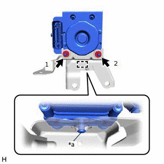
*a
Pin
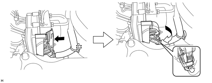
Install a new brake actuator assembly to the brake actuator bracket assembly and engage the pin.
Note:Do not remove the hole plugs of a new brake actuator assembly before connecting the brake lines because the brake actuator assembly is filled with brake fluid.
Do not hold the brake actuator assembly by the connector.
Be sure to insert the pin of the brake actuator assembly to the cushion of the brake actuator bracket assembly.
Tighten the 2 nuts to secure the brake actuator assembly to the brake actuator bracket assembly.
7.5 N*m
76 kgf*cm
66 in.*lbf
Note:Tighten the 2 nuts in the order shown in the illustration.
-
INSTALL BRAKE ACTUATOR WITH BRACKET
-
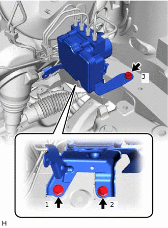
Install the brake actuator with bracket with the 3 bolts.
19 N*m
194 kgf*cm
14 ft.*lbf
Note:Do not damage the brake lines.
Do not hold the brake actuator with bracket by the connector.
Tighten the 3 bolts in the order shown in the illustration.
Tip:Install the brake actuator with bracket while avoiding the brake lines.
Engage the clamp to install the No. 3 fuel tube clamp to the brake actuator bracket assembly.
-
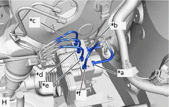
*a
for LHD: From 1st Chamber of Brake Master Cylinder Sub-assembly
for RHD: From 2nd Chamber of Brake Master Cylinder Sub-assembly
*b
for LHD: From 2nd Chamber of Brake Master Cylinder Sub-assembly
for RHD: From 1st Chamber of Brake Master Cylinder Sub-assembly
*c
To Front Wheel Cylinder Assembly RH
*d
To Rear Wheel Cylinder Assembly LH
*e
To Rear Wheel Cylinder Assembly RH
*f
To Front Wheel Cylinder Assembly LH
Temporarily tighten the 6 brake lines to the correct positions on the brake actuator assembly as shown in the illustration.
-
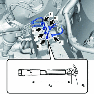
*a
Torque Wrench Fulcrum Length
*b
Union Nut Wrench
Using a union nut wrench, fully tighten each brake line.
Specified tightening torque (A)
19.5 N*m
199 kgf*cm
14 ft.*lbf
Specified tightening torque (B)
15.2 N*m
155 kgf*cm
11 ft.*lbf
Note:Do not kink or damage the brake lines.
Tip:Calculate the torque wrench reading when changing the fulcrum length of the torque wrench.
When using a union nut wrench (fulcrum length of 20 mm (0.787 in.)) + torque wrench (fulcrum length of 162 mm (6.38 in.)):
(A): 17.4 N*m (177 kgf*cm, 13 ft.*lbf)
When using a union nut wrench (fulcrum length of 22 mm (0.866 in.)) + torque wrench (fulcrum length of 162 mm (6.38 in.)):
(B): 13.4 N*m (137 kgf*cm, 10 ft.*lbf)
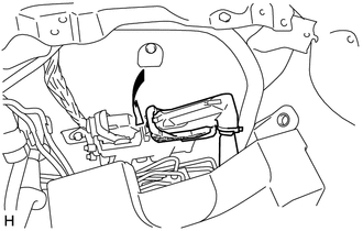
Connect the connector to the brake actuator assembly.
Pull the lock lever down and engage the claw of the lock lever to engage the connector lock.
Note:Make sure that the connector is locked securely.
Make sure that the actuator connector can be connected smoothly. Do not allow water, oil or dirt to enter the connector.
Engage the wire harness clamp.
for RHD:
-
Connect the connector to the ECM and lower the lever.
Note:When connecting the connector to the ECM, make sure that dirt, water or other foreign matter does not contact the connecting part of the connector.
Be sure to securely connect the connector.
-
-
INSTALL RELAY BLOCK BRACKET
Install the relay block bracket with the bolt.
8.4 N*m
86 kgf*cm
74 in.*lbf
Install the ground wire to the relay block bracket with the bolt.
8.4 N*m
86 kgf*cm
74 in.*lbf
INSTALL BRAKE MASTER CYLINDER SUB-ASSEMBLY (for LHD)
INSTALL BATTERY CLAMP SUB-ASSEMBLY
INSTALL BATTERY
INSTALL OUTER COWL TOP PANEL
for LHD:Click here
for RHD:Click here
INSTALL FRONT NO. 1 VENTILATOR SEAL
for LHD:Click here
for RHD:Click here
INSTALL FRONT AIR SHUTTER SEAL RH
for LHD:Click here
for RHD:Click here
INSTALL FRONT WIPER MOTOR AND LINK ASSEMBLY
CONNECT CABLE TO NEGATIVE BATTERY TERMINAL
Note:When disconnecting the cable, some systems need to be initialized after the cable is reconnected.
BLEED BRAKE SYSTEM
PERFORM SYSTEM VARIANT LEARNING AND ACCELERATION SENSOR ZERO POINT CALIBRATION
PERFORM TEST MODE INSPECTION
INSPECT BRAKE ACTUATOR USING GTS
CHECK FOR AND CLEAR DTCS