LOWER INSTRUMENT PANEL INSTALLATION
CAUTION / NOTICE / HINT
Use the same procedure for RHD and LHD vehicles.
The procedure listed below is for LHD vehicles.
PROCEDURE
INSTALL GLOVE COMPARTMENT DOOR LOCKCYLINDER ASSEMBLY (for RHD)
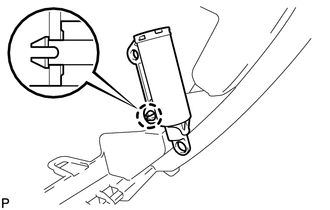
Insert the end of the glove compartment door lock cylinder as shown in the illustration, hold down the stopper and install the glove compartment door lock cylinder.
INSTALL GLOVE COMPARTMENT DOOR STOPPER SUB-ASSEMBLY
Attach the claw to install the glove compartment door stopper.
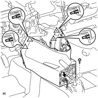
INSTALL LOWER INSTRUMENT PANEL SUB-ASSEMBLY
for LHD:
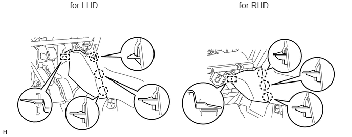
Attach the 6 guides to install the lower instrument panel.
Install the 4 screws <D> and 2 bolts <B>.
Install the 11 bolts <C>.
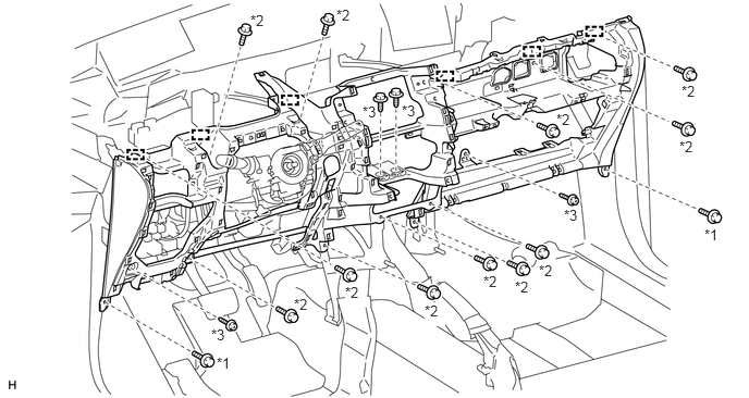
Table 1. Text in Illustration *1
Bolt <B>
*2
Bolt <C>
*3
Screw <D>
-
-
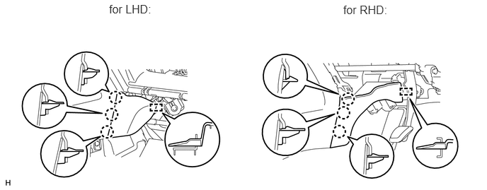
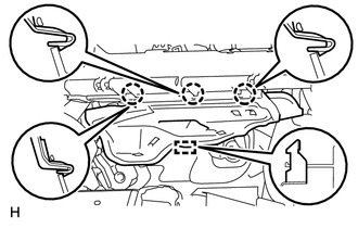
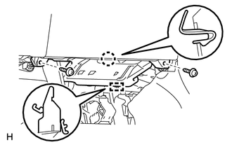
Connect the connectors and clamps.
Connect the hood lock control cable and DLC3.
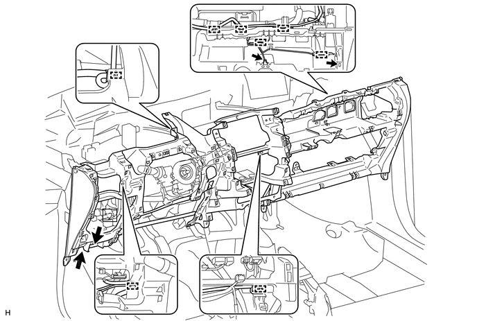
Table 2. Text in Illustration *1
Hood Lock Control Cable
*2
DLC3
for RHD:
Attach the 6 guides to install the lower instrument panel.
Install the 4 screws <D> and 2 bolts <B>.
Install the 11 bolts <C>.
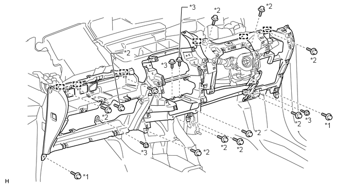
Table 3. Text in Illustration *1
Bolt <B>
*2
Bolt <C>
*3
Screw <D>
-
-
Connect the connector and clamps.
Connect the hood lock control cable and DLC3.
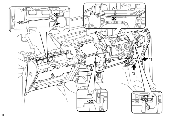
Table 4. Text in Illustration *1
Hood Lock Control Cable
*2
DLC3
except Manual Transaxle:
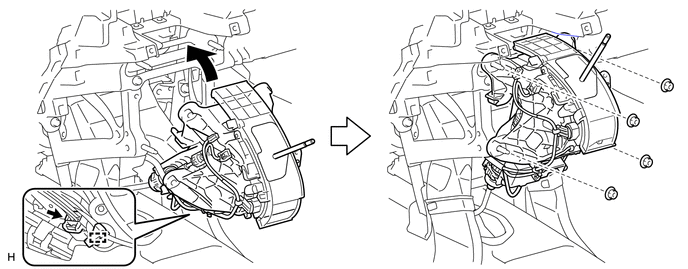
Connect the connector and attach the clamp.
Install the shift lever assembly with the 4 nuts.
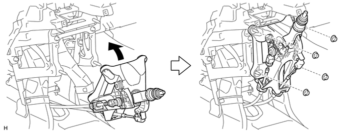
for Manual Transaxle:
Install the shift lever assembly with the 4 nuts.
INSTALL LOWER NO. 1 INSTRUMENT PANEL FINISH PANEL
Attach the 4 clips to install the lower No. 1 instrument panel finish panel.
Connect the connector.
Install the screw <D>.
INSTALL FRONT NO. 2 CONSOLE BOX INSERT
Attach the 3 claws and guide to install the front No. 2 console box insert.
INSTALL FRONT NO. 1 CONSOLE BOX INSERT
Attach the 3 claws and guide to install the front No. 1 console box insert.
INSTALL AIR CONDITIONER CONTROL ASSEMBLY (for Automatic Air Conditioning System)
INSTALL CENTER INSTRUMENT CLUSTER FINISH PANEL ASSEMBLY (for Manual Air Conditioning System)
INSTALL GLOVE COMPARTMENT DOOR ASSEMBLY
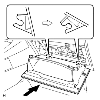
Attach the 2 hinges to install the glove compartment door.
-
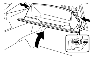
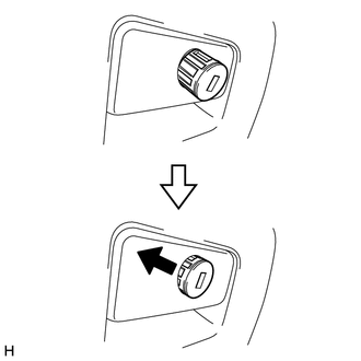
Attach the glove compartment door stopper to the glove compartment door as shown in the illustration.
While pushing in the sides of the glove compartment door as indicated by the arrows in the illustration, close the glove compartment door to engage the 2 stoppers.
Table 5. Text in Illustration *1
Stopper
INSTALL NO. 2 INSTRUMENT PANEL UNDER COVER SUB-ASSEMBLY
Attach the 3 claws and guide to install the No. 2 instrument panel under cover.
INSTALL LOWER NO. 1 INSTRUMENT PANEL AIRBAG ASSEMBLY
INSTALL FUSE BOX OPENING COVER
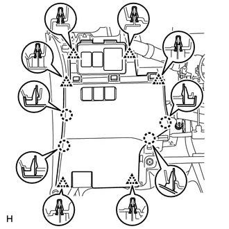
for LHD:
Connect the connectors.
Attach the 6 clips and 4 claws to install the fuse box opening cover.
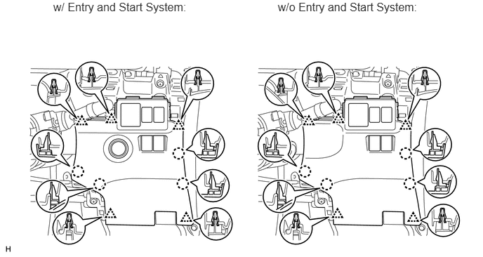
for RHD:
Connect the connectors.
Attach the 5 clips and 4 claws to install the fuse box opening cover.
INSTALL NO. 1 INSTRUMENT PANEL UNDER COVER SUB-ASSEMBLY
Attach the claw and guide to install the No. 1 instrument panel under cover.
Install the 2 screws <A>.
INSTALL UPPER STEERING COLUMN COVER
INSTALL LOWER STEERING COLUMN COVER
INSTALL STEERING WHEEL ASSEMBLY
INSTALL STEERING PAD
INSTALL BOX PANEL SUB-ASSEMBLY
Install the box panel sub-assembly (Click here).
INSTALL INSTRUMENT PANEL SAFETY PAD SUB-ASSEMBLY
Install the instrument panel safety pad sub-assembly (Click here).
CONNECT CABLE TO NEGATIVE BATTERY TERMINAL
Note:When disconnecting the cable, some systems need to be initialized after the cable is reconnected (Click here).
CHECK SRS WARNING LIGHT
Check the SRS warning light (Click here).