HYBRID CONTROL SYSTEM, Diagnostic DTC:P0069-273
| DTC Code | DTC Name |
|---|---|
| P0069-273 | Manifold Absolute Pressure - Barometric Pressure Correlation |
DESCRIPTION
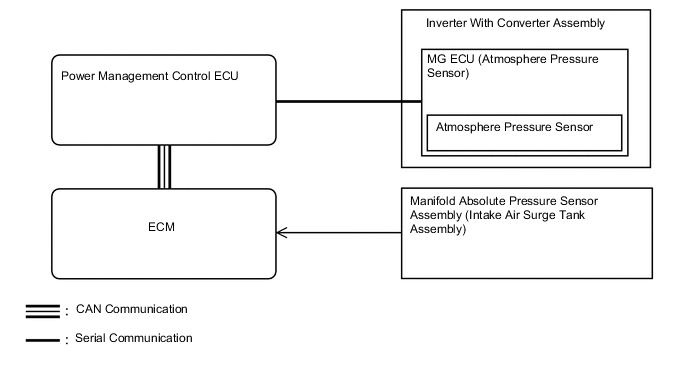
The atmospheric pressure sensor mounted on the MG ECU circuit board detects the atmospheric pressure. This reading is used to perform system control that considers vehicle usage conditions.
| DTC No. | INF Code | DTC Detection Condition | Trouble Area |
|---|---|---|---|
| P0069 | 273 | Difference between the atmospheric pressure value of the atmospheric pressure sensor in the inverter with converter assembly and the manifold absolute pressure sensor (for EGR control) exceeds a specified value. The same condition recurs within 3 hours when driving in EV mode. |
|
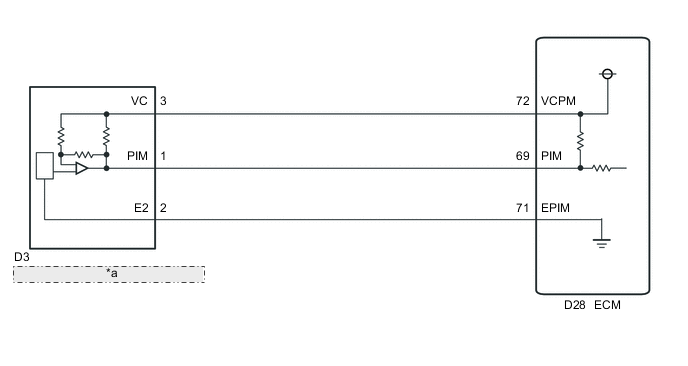
WIRING DIAGRAM
| *a | Manifold Absolute Pressure Sensor |
CAUTION / NOTICE / HINT
Tech Tips
After the repair, perform the following procedure to confirm the repair.
-
If the values of Data List items "Atmosphere Pressure" and "MAP" are almost the same with the engine stopped and the power switch on (IG), those sensors are normal.
-
If the values of Data List items "Atmosphere Pressure" and "MAP" are still difference 10 kPa or more after after replacing components of the inverter with converter assembly, replace the inverter with converter assembly.
PROCEDURE
-
CHECK DTC OUTPUT (ENGINE AND ECT)
-
Connect the GTS to the DLC3.
-
Turn the power switch on (READY).
-
Fully depress the accelerator pedal for 5 seconds to start the engine and keep it running.
-
Enter the following menus: Powertrain / Engine and ECT / Trouble Codes.
-
Check if DTCs are output.
Result Result Proceed to DTCs other than those listed in the following table are output. A Any of the following DTCs are also output. B DTC No. Relevant Diagnosis P0107 Manifold Absolute Pressure/Barometric Pressure Circuit Low Input P0108 Manifold Absolute Pressure/Barometric Pressure Circuit High Input Tech Tips
P0069-273 may be output due to a malfunction which causes the DTCs in the table above to be output. In this case, first troubleshoot the output DTCs in the table above. Then, perform a reproduction test to check that no DTCs are output.
-
Turn the power switch off.
B 
GO TO DTC CHART (SFI SYSTEM) Click here
A 
-
-
CHECK DTC OUTPUT (HYBRID CONTROL)
-
Connect the GTS to the DLC3.
-
Turn the power switch on (IG).
-
Enter the following menus: Powertrain / Hybrid Control / Trouble Codes.
-
Check if DTCs are output.
Result Result Proceed to DTC P0069-273 only is output, or DTCs other than the ones in the table below are also output. A Any of the following DTCs are also output. B DTC No. Relevant Diagnosis P0A1A-151, 155, 156, 658, 659 Generator Control Module P0A1B-193, 512, 661, 786 Drive Motor "A" Control Module P0A1D-148 Hybrid Powertrain Control Module P2228-268 Barometric Pressure Sensor "A" Circuit Low P2229-269 Barometric Pressure Sensor "A" Circuit High P2511-149 HV CPU Power Relay Sensor Circuit Intermittent No Continuity P324E-788 MG-ECU Power Relay Intermittent Circuit U0100-211, 530 Lost Communication with ECM/PCM "A" U0110 (all INF codes)*1 Lost Communication with Drive Motor Control Module "A" Tech Tips
-
*1: If any INF codes are output for this DTC, refer to the corresponding diagnostic procedure.
-
P0069-273 may be output due to a malfunction which causes the DTCs in the table above to be output. In this case, first troubleshoot the output DTCs in the table above. Then, perform a reproduction test to check that no DTCs are output.
-
-
Turn the power switch off.
B
GO TO DTC CHART (HYBRID CONTROL SYSTEM) Click here
A
-
-
READ VALUE USING GTS (MAP, ATMOSPHERE PRESSURE)
-
Connect the GTS to the DLC3.
-
Turn the power switch on (IG).
-
Enter the following menus: Powertrain / Hybrid Control / Data List / MAP, Atmosphere Pressure.
-
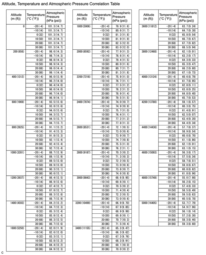
Using the table, read the normal atmospheric pressure value for the applicable altitude.
-
Compare the MAP and Atmosphere Pressure values in the Data List with the normal atmospheric value from the table.
Result Result Proceed to Other than the following. A Difference between MAP in Data List and normal atmospheric pressure value is 10 kPa or more. B Difference between Atmosphere Pressure in Data List and normal atmospheric pressure value is 10 kPa or more. C -
Turn the power switch off.
B 
CHECK TERMINAL VOLTAGE (POWER SOURCE OF MANIFOLD ABSOLUTE PRESSURE SENSOR) Click here
C
REFER TO REPLACE INVERTER WITH CONVERTER ASSEMBLY PARTS Click here
A
-
-
READ VALUE USING GTS (MAP)
-
Push the P position switch.
-
Enter the following menus: Powertrain / Hybrid Control / Data List / MAP
-
Read the MAP value in the Data List with the engine stopped.
-
While depressing the brake pedal, turn the power switch on (READY).
-
With the READY indicator light illuminated, fully depress the accelerator pedal.
-
Read the MAP value in the Data List with the engine running.
-
Compare the MAP value noted with the engine stopped and the MAP value noted with the engine running.
OK The MAP value changes (pressure decreases when the engine is started). -
Turn the power switch off.
NG
CHECK TERMINAL VOLTAGE (POWER SOURCE OF MANIFOLD ABSOLUTE PRESSURE SENSOR) Click here
OK
-
-
REPLACE MANIFOLD ABSOLUTE PRESSURE SENSOR
NEXT
-
READ VALUE USING GTS (MAP, ATMOSPHERE PRESSURE)
-
Connect the GTS to the DLC3.
-
Turn the power switch on (IG).
-
Enter the following menus: Powertrain / Hybrid Control / Data List / MAP, Atmosphere Pressure.
-
Compare the Data List item "MAP" with "Atmosphere Pressure".
Result Result Proceed to The difference between "MAP" and "Atmosphere Pressure" is 10 kPa or more. A The difference between "MAP" and "Atmosphere Pressure" is less than 10 kPa. B -
Turn the power switch off.
A
REFER TO REPLACE INVERTER WITH CONVERTER ASSEMBLY PARTS Click here
B
COMPLETED
-
-
CHECK TERMINAL VOLTAGE (POWER SOURCE OF MANIFOLD ABSOLUTE PRESSURE SENSOR)
-
Disconnect the D3 manifold absolute pressure sensor connector.
-
Turn the power switch on (IG).
-
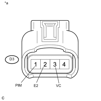
Text in Illustration *a Front view of wire harness connector
(to Manifold Absolute Pressure Sensor)
Measure the voltage according to the value(s) in the table below.
Standard Voltage Tester Connection Condition Specified Condition D3-3 (VC) - D3-2 (E2) Power switch on (IG) 4.5 to 5.5 V D3-1 (PIM) - D3-2 (E2) Power switch on (IG) 3.0 to 5.0 V Result Result Proceed to NG A OK B -
Reconnect the D3 manifold absolute pressure sensor connector.
B
REPLACE MANIFOLD ABSOLUTE PRESSURE SENSOR Click here
A
-
-
CHECK HARNESS AND CONNECTOR (MANIFOLD ABSOLUTE PRESSURE SENSOR - ECM)
-
Disconnect the D3 manifold absolute pressure sensor connector.
-
Disconnect the D28 ECM connector.
-
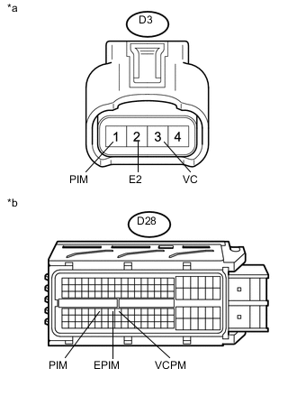
Text in Illustration *a Front view of wire harness connector
(to Manifold Absolute Pressure Sensor)
*b Front view of wire harness connector
(to ECM)
Measure the resistance according to the value(s) in the table below.
Standard Resistance Tester Connection Condition Specified Condition D3-3 (VC) - D28-72 (VCPM) Always Below 1 Ω D3-2 (E2) - D28-71 (EPIM) Always Below 1 Ω D3-1 (PIM) - D28-69 (PIM) Always Below 1 Ω D3-3 (VC) or D28-72 (VCPM) - Body ground Always 10 kΩ or higher D3-2 (E2) or D28-71 (EPIM) - Body ground Always 10 kΩ or higher D3-1 (PIM) or D28-69 (PIM) - Body ground Always 10 kΩ or higher -
Reconnect the D28 ECM connector.
-
Reconnect the D3 manifold absolute pressure sensor connector.
OK
REPLACE ECM Click here
NG
REPAIR OR REPLACE HARNESS OR CONNECTOR
-
-
REPLACE MANIFOLD ABSOLUTE PRESSURE SENSOR
NEXT
-
CLEAR DTC
-
Connect the GTS to the DLC3.
-
Turn the power switch on (IG).
-
Enter the following menus: Powertrain / Hybrid Control / Trouble Codes.
-
Read and record the DTCs and freeze frame data.
-
Clear DTCs and freeze frame data.
-
Turn the power switch off.
NEXT
-
-
CHECK DTC OUTPUT (HYBRID CONTROL)
-
Connect the GTS to the DLC3.
-
Turn the power switch on (IG).
-
Enter the following menus: Powertrain / Hybrid Control / Trouble Codes.
-
Check if DTCs are output.
Result Result Proceed to DTC P0069-273 is not output. A DTC P0069-273 is output. B -
Turn the power switch off.
A
COMPLETED
B
REPLACE ECM Click here
-