REAR LOWER ARM REMOVAL

CAUTION / NOTICE / HINT
The necessary procedures (adjustment, calibration, initialization, or registration) that must be performed after parts are removed, installed, or replaced during the rear lower arm removal/installation are shown below.
| Necessary Procedure After Parts Removed/Installed/Replaced | ||||||||||||||||||||||
|---|---|---|---|---|---|---|---|---|---|---|---|---|---|---|---|---|---|---|---|---|---|---|
|
Tech Tips
-
Use the same procedure for the RH and LH side.
-
The following procedure is for the LH side.
PROCEDURE
-
AIR SUSPENSION CONTROL PROHIBITED (w/ Air Suspension)
-
REMOVE REAR WHEEL
-
REMOVE NO. 2 DIFFERENTIAL SUPPORT PROTECTOR
-
REMOVE LOWER CONTROL ARM ASSEMBLY LH
-
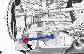
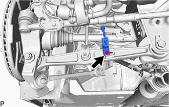
Remove the nut.
-
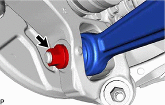
Install 2 SST (spacer B) onto the lower control arm assembly LH so that there is a space of approximately 1 mm (0.0394 in.) between the arm and spacers.
- SST
- 09960-20010 ( 09961-02060 )
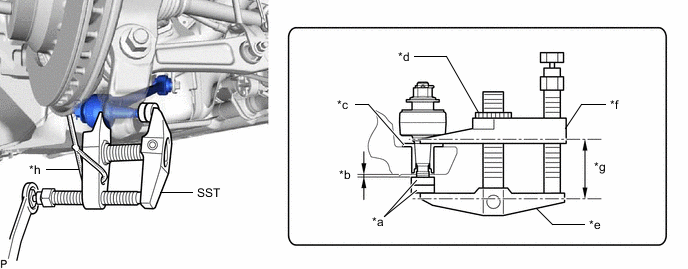
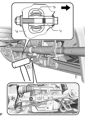
*a SST (Spacer B) *b 1 mm (0.0394 in.) *c Spacer *d Center Nut *e Body *f Claw *g Parallel *h String Note
-
Make sure to install the spacers (SST spacer A) as the rear axle carrier sub-assembly LH spacer may shift.
-
As SST may become damaged, make sure the space between the arm and spacers is not 1 mm (0.0394 in.) or less.
-
Using SST, disconnect the lower control arm assembly LH from the rear axle carrier sub-assembly LH.
- SST
- 09960-20010 ( 09961-02010 )
Note
-
Apply molybdenum grease to the bolt threads and end of the SST bolt.
-
Do not damage the dust cover.
-
As the dust cover may be damaged, adjust SST with the center nut so that the body and claw are parallel.
-
Make sure to tie the string of SST to the vehicle to prevent SST from dropping.
-

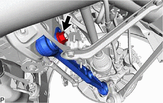
Bolt 
Nut Remove the bolt, nut and lower control arm assembly LH.
Note
Because the nut has its own stopper, do not turn the nut. Loosen the bolt with the nut secured.
-
-
DISCONNECT REAR STABILIZER LINK ASSEMBLY LH
-
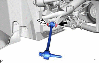
Remove the bolt and nut, disconnect rear stabilizer link assembly LH from the rear No. 2 suspension arm assembly LH.
-
-
DISCONNECT REAR HEIGHT CONTROL SENSOR SUB-ASSEMBLY LH
-
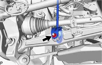
Remove the bolt and disconnect rear height control sensor sub-assembly LH from the rear No. 2 suspension arm assembly LH.
-
-
DISCONNECT REAR HEIGHT CONTROL SENSOR SUB-ASSEMBLY RH (w/ AVS)
Tech Tips
Use the same procedure for the RH side and LH side.
-
REMOVE REAR NO. 2 SUSPENSION ARM ASSEMBLY LH
-
Loosen the nut.
-
*a A *b Arm *c Slide Pin *d Axle Carrier Front of the Vehicle Using a plastic-faced hammer or equivalent, strike the part labeled A from the rear of the vehicle to maintain the clearance at the slide pin area.
Note
Be careful not to damage the arm.
-
Remove the nut, bolt and washer.
-
Remove the nut, rear No. 2 suspension toe adjust plate, rear suspension arm attachment sub-assembly and rear No. 2 suspension arm assembly LH.
-