FRONT DOOR ADJUSTMENT
Tech Tips
-
Use the same procedure for the RH and LH sides.
-
The procedure listed below is for the LH side.
-
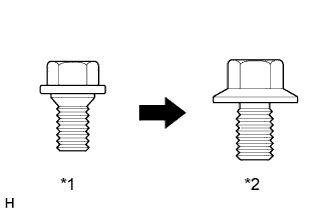
Centering bolts are used to mount the door hinge to the vehicle body and door. The door cannot be adjusted with the centering bolts on. Substitute the centering bolts for standard bolts when making adjustments.
-
A bolt without a torque specification is shown in the standard bolt chart Click here.
| *1 | Centering Bolt |
| *2 | Standard Bolt |
-
INSPECT FRONT DOOR PANEL SUB-ASSEMBLY LH
-
Check that the clearance measurements of areas A to M are within the standard ranges.
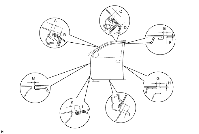
Standard Area Specified Condition Area Specified Condition A 3.6 to 6.6 mm (0.142 to 0.260 in.) B 1.5 to 4.5 mm (0.0591 to 0.177 in.) C 3.6 to 6.6 mm (0.142 to 0.260 in.) D *1: 1.2 to 4.2 mm (0.0472 to 0.165 in.)
*2: 1.1 to 4.1 mm (0.0433 to 0.161 in.)
E *1: 3.0 to 6.0 mm (0.118 to 0.236 in.)
*2: 3.5 to 6.5 mm (0.138 to 0.256 in.)
F -1.5 to 1.5 mm (-0.0591 to 0.0591 in.) G *1: 3.0 to 6.0 mm (0.118 to 0.236 in.)
*2: 3.5 to 6.5 mm (0.138 to 0.256 in.)
H -1.5 to 1.5 mm (-0.0591 to 0.0591 in.) I 3.7 to 6.7 mm (0.146 to 0.264 in.) J 7.5 to 10.5 mm (0.295 to 0.413 in.) K 3.2 to 6.2 mm (0.126 to 0.244 in.) L 1.0 to 4.0 mm (0.0394 to 0.158 in.) M 3.1 to 6.1 mm (0.122 to 0.240 in.) - - *1: for Single Cab, for Extra Cab
*2: for Double Cab
-
-
ADJUST FRONT DOOR PANEL SUB-ASSEMBLY LH
-
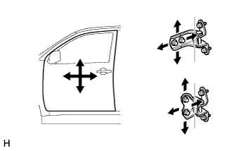
Using SST, loosen the hinge bolts on the body and adjust the door position.
- SST
- 09812-00010
-
Tighten the hinge bolts on the body after the adjustment.
- Torque:
- 26 N*m { 265 kgf*cm, 19 ft.*lbf }
-
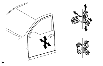
Loosen the hinge bolts on the door and adjust the door position.
-
Tighten the hinge bolts on the door after the adjustment.
- Torque:
- 26 N*m { 265 kgf*cm, 19 ft.*lbf }
-
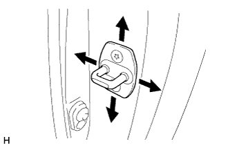
Using a T30 "TORX" socket, adjust the striker position by slightly loosening the striker mounting screws and hitting the striker with a plastic-faced hammer.
-
Using a T30 "TORX" socket, tighten the striker mounting screws after the adjustment.
- Torque:
- 23 N*m { 235 kgf*cm, 17 ft.*lbf }
-