AUTOMATIC TRANSAXLE SYSTEM
-
FUNCTION OF MAIN COMPONENTS
Component Function Shift Solenoid Valve SL1 Controls the No. 1 clutch (C1) pressure. Shift Solenoid Valve SL2 Controls the No. 2 clutch (C2) pressure. Shift Solenoid Valve SL3
-
Controls the No. 2 brake (B2) pressure.
-
Controls the No. 3 clutch (C3) pressure.
Shift Solenoid Valve SL4 Controls the No. 4 clutch (C4) pressure. Shift Solenoid Valve SL5 Controls the No. 1 brake (B1) pressure. Shift Solenoid Valve SLT (Line Pressure Control Solenoid Assembly)
-
Controls line pressure.
-
Switches the No. 1 clutch apply relay valve.
Shift Solenoid Valve SLU (Lock-up Control Solenoid Assembly)
-
Controls the lock-up clutch pressure.
-
Switches the lock-up relay valve.
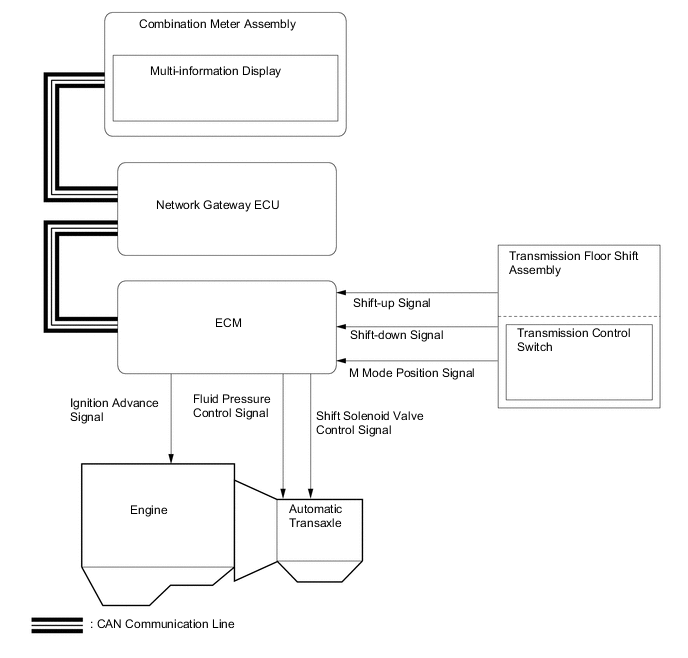
Shift Solenoid Valve S1 Switches the C3-B2 clutch apply control valve. Shift Solenoid Valve S2 Switches the B2 apply control valve. Transmission Revolution Sensor (NT) Detects the input speed of the transaxle. Transmission Revolution Sensor (NC) Detects the speed of the counter gear. Transmission Revolution Sensor (NC3) Detects the C3 clutch dram. ATF Temperature Sensor Detects the ATF temperature. Accelerator Pedal Sensor Assembly Detects the accelerator pedal opening angle. Throttle Body with Motor Assembly Throttle Position Sensor Detects the throttle valve opening angle. Intake Mass Air Flow Meter Sub-assembly Detects the intake air volume and intake air temperature. Crank Position Sensor Detects the engine speed and performs the cylinder identification. Engine Coolant Temperature Sensor Detects the engine coolant temperature. Park/Neutral Position Switch Assembly Detects the shift lever position. Transmission Floor Shift Assembly Transmission Control Switch
-
Detects when the shift lever is in M.
-
Detects the shift-up and shift-down operations performed by the driver when the shift lever is in M.
Cruise Control Main Switch Turns the cruise control system on and off, and conducts various operations including vehicle speed setting, acceleration, deceleration and control cancellation. Stop Light Switch Assembly Detects when the brake pedal is depressed. Combination Switch Assembly Drive Mode Select
-
Outputs the NORMAL or SPORT mode signal to the ECM when operated by the driver.
-
Outputs the ECO mode signal to the ECM via the air conditioning amplifier assembly when operated by the driver.
ECM
-
Controls engine output and each shift solenoid valve in response to a signal from each sensor and switch.
-
Makes a diagnosis and memorizes the failed section when the ECM detects a malfunction.
Air Conditioning Amplifier Assembly Transmits various air conditioning state signals to the ECM. Airbag Sensor Assembly
-
Detects the vehicle's longitudinal and lateral acceleration.
-
Detects the vehicle's yaw rate.
Driving Support ECU Assembly* Sends the information about the operation conditions of the dynamic radar cruise control system to the ECM. Combination Meter Assembly Malfunction Indicator Lamp (MIL) Illuminates to inform the driver when the ECM detects a malfunction. Master Warning Light Warns the driver by lighting up when a message is shown on the multi-information display. Multi-information Display
-
Displays the shift lever position.
-
Displays the shift range.
-
Displays the drive mode.
-
Warns the driver by displaying a message when the ATF is at a high temperature.
Buzzer
-
Sounds when the shift-down operation is rejected.
-
Warns the driver by sounding when a message is shown on the multi-information display.
Accessory Meter Assembly Displays the drive mode. *: Models with pre-crash safety system
-
-
SYSTEM CONTROL
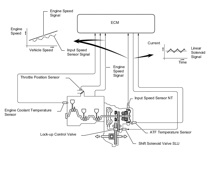
Electronic Control of Automatic Transaxle Control Outline Shift Timing Control The ECM sends current to shift solenoid valves SL1, SL2, SL3, SL4, SL5, S1, S2 and/or SLU based on signals from various sensors, in order to shift the gears. Clutch Pressure Control
-
Controls the pressure that is applied directly to the C1, C2, C3, C4 clutches and B1, B2 brakes by actuating the shift solenoid valves (SL1, SL2, SL3, SL4 and SL5) in accordance with signals from the ECM.
-
The solenoid valve SLT, SLU, SL1, SL2, SL3, SL4 and SL5 minutely control the clutch pressure in accordance with the engine output and driving conditions.
Line Pressure Control Actuates shift solenoid valve SLT to control the line pressure in accordance with information from the ECM and the operating conditions of the transaxle. Lock-up Timing Control The ECM sends current to shift solenoid valve SLU based on signals from various sensors to engage or disengage the lock-up clutch. Flex Lock-up Clutch Control Controls shift solenoid valve SLU, provides an intermediate mode between the on and off states of the lock-up clutch, and increases the operating range of the lock-up clutch to improve fuel economy. Powertrain Cooperative Control Controls both the shift control and engine output control in an integrated way achieving excellent shift characteristics and drivability. Deceleration Downshift Control The ECM performs downshift control so that fuel cut control can continue for as long as possible during deceleration. Direct Downshift Control Direct downshift control is used. This makes it possible to skip unnecessary shifts, enabling the vehicle to downshift directly from 7th to 4th enhancing downshift response when the accelerator pedal is depressed quickly. Artificial Intelligence Shift Control (AI-shift Control) Based on the signals from various sensors, the ECM determines the road conditions and the intention of the driver. Thus, an appropriate shift pattern is automatically determined, improving drivability. (This control is in effect only with the shift lever in D. When moving the shift lever to M, this control will be canceled.) Multi-mode Automatic Transmission
-
When the shift lever is moved to M, driving in a gear position selected using the shift lever is enabled.
-
Gear hold control, super high response upshift control and blipping downshift control are used to produce a direct feeling in response to accelerator and gear shift operation.
-
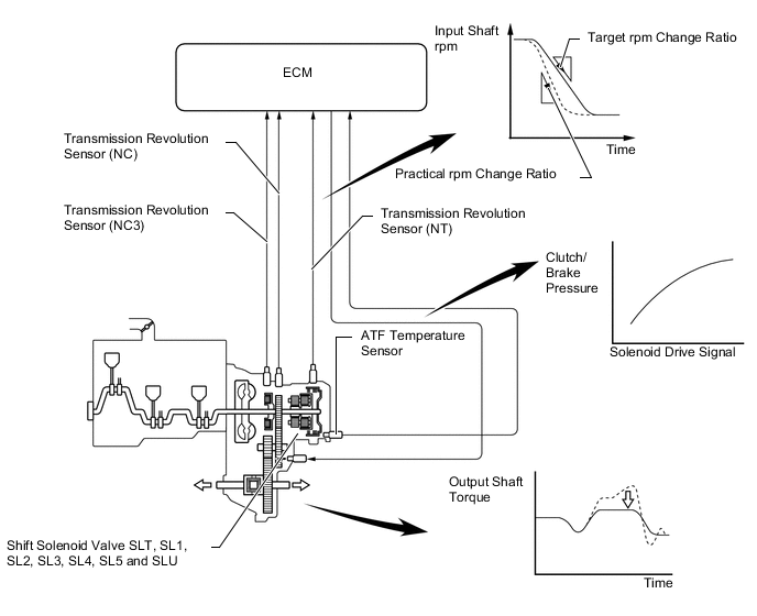
Clutch Pressure Control
-
The ECM monitors the signals from various types of sensors, such as the transmission revolution sensor (NT), transmission revolution sensor (NC) and transmission revolution sensor (NC3), allowing linear solenoid valves SLT, SL1, SL2, SL3, SL4, SL5 and SLU to minutely control the clutch pressure in accordance with engine output and driving conditions. As a result, smooth shift characteristics have been realized.
-
-
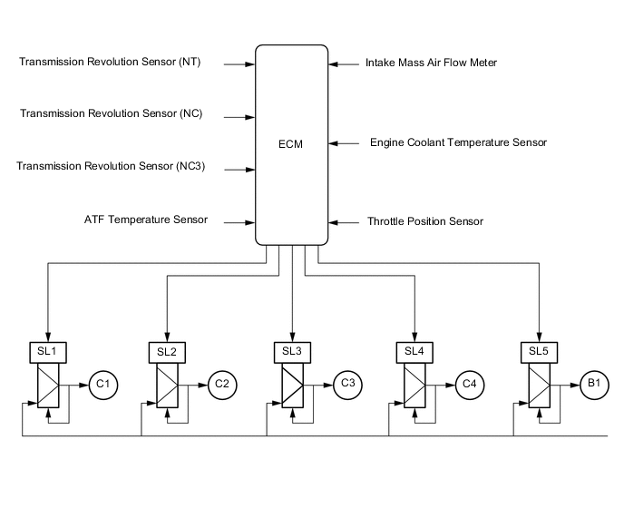
Clutch to Clutch Pressure Control
-
Clutch to clutch pressure control is used for shift control. As a result, shift control in 2nd gear or above is possible without using a one-way clutch, making the automatic transaxle lightweight and compact.
-
Using the fluid pressure circuit, which enables the clutches and brake (C1, C2, C3, C4 and B1) to be controlled independently, and the high flow SL1, SL2, SL3, SL4 and SL5 linear solenoid valves, which directly control the line pressure, the ECM controls each clutch and brake accordingly with the optimum fluid pressures and timings in accordance with the information transmitted by the sensors, and then shifts the gears. As a result, highly responsive and excellent shift characteristics have been realized.
-
-
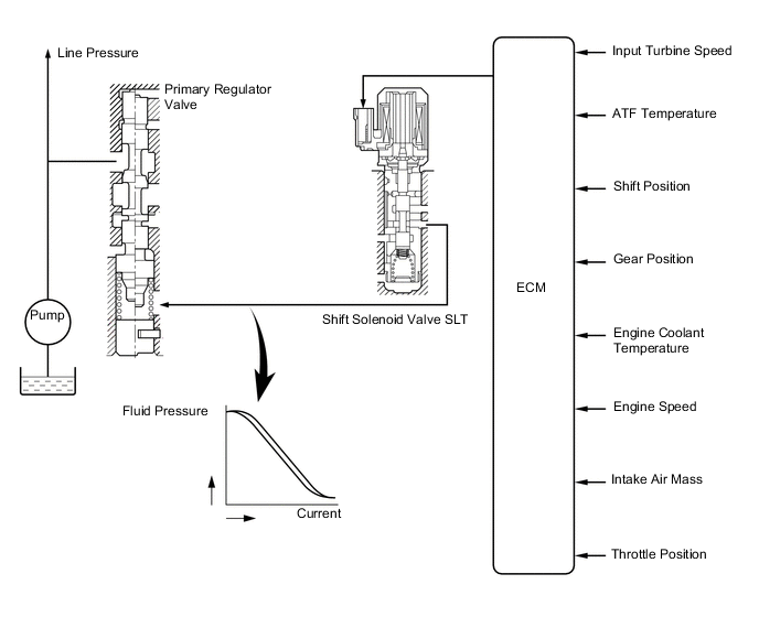
Line Pressure Control
-
The line pressure is controlled using shift solenoid valve SLT.
-
Through the use of shift solenoid valve SLT, the line pressure is appropriately controlled in accordance with the engine torque information, as well as with the internal operating conditions of the torque converter and the transaxle.
-
Accordingly, the line pressure can be accurately controlled in accordance with the engine output, driving condition, and the ATF temperature, thus realizing smooth shift characteristics and regulating the workload of the oil pump (reducing unnecessary parasitic losses).
-
-
Lock-up Timing Control
-
The ECM uses lock-up timing control in order to improve the fuel consumption performance in 3rd gear or higher when the shift lever is in D range has been selected.
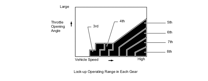
Lock-up Operation Gear Position Shift Lever Position D 1st X 2nd X 3rd ○ 4th ○ 5th ○ 6th ○ 7th ○ 8th ○ ○: Operates
X: Does not operate
-
-
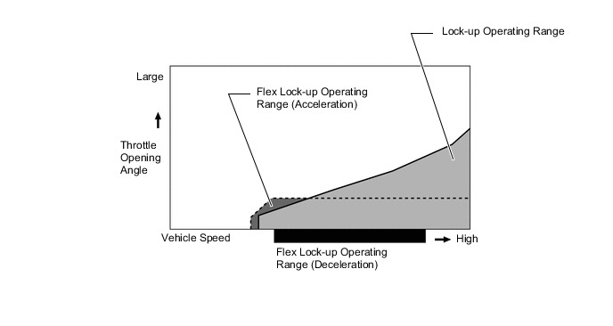
Flex Lock-up Clutch Control
-
During acceleration, the partial control of the power transaxle between the lock-up clutch and torque converter greatly boosts the transmission efficiency in accordance with the driving conditions, improving the fuel economy.
-
Even when the vehicle is decelerating (the accelerator pedal is released), flex lock-up clutch control operates. Therefore, the fuel-cut area of the engine has been expanded and fuel-economy has been improved.
-
By allowing flex lock-up clutch control to continue operating during gearshifts, smooth torque transmission has been obtained. As a result, fuel economy and drivability have been improved.
-
For flex lock-up control, H infinity (H∞) control theory is used to achieve a high level of system stability and response to various characteristic changes.
-
The flex lock-up operating range has been expanded. Flex lock-up begins operating once the vehicle starts moving to lower engine speed and improve fuel economy.
Flex Lock-up Operation Gear Position Shift Lever Position D 1st X 2nd X 3rd ○ 4th ○* 5th ○* 6th ○* 7th ○* 8th ○* ○: Operates
X: Does not operate
*: Flex lock-up clutch control also operates when the vehicle decelerates.
-
-
Powertrain Cooperative Control
-
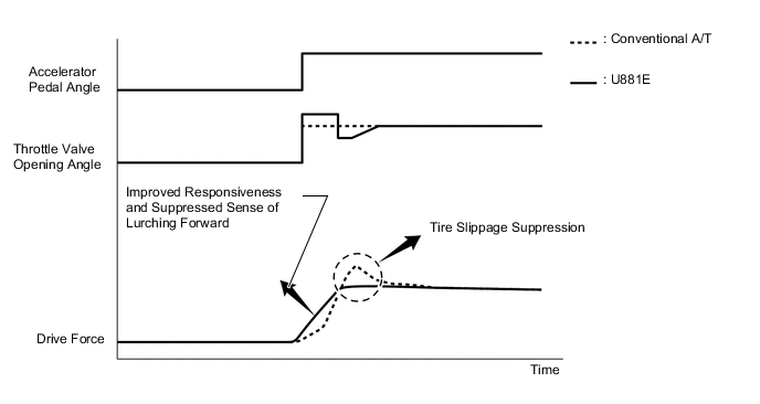
Throttle Control at Launch
-
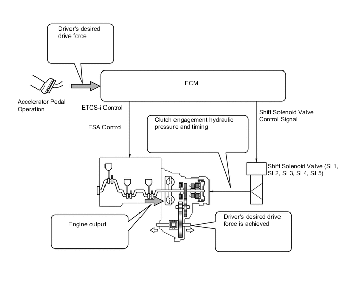
The engine output is appropriately controlled with Electronic Throttle Control System-intelligent (ETCS-i) in real-time according to the transient force from the torque converter when the vehicle is launched. This achieves a "suppressed sense of lurching forward", "tire slippage suppression" and "improved responsiveness", ensuring excellent launch performance.
-
-
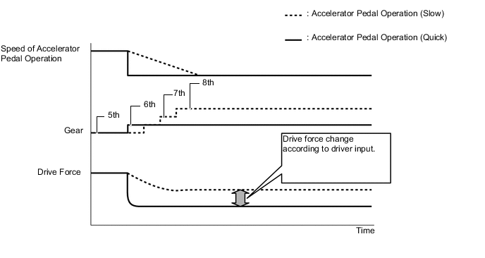
Deceleration Force Control
-
The ECM determines the gear that is to be selected when the accelerator pedal is released (released completely) in accordance with the way the accelerator pedal is released (quickly or slowly) during deceleration. In this way, unnecessary upshifts are prevented during deceleration, matching the driver's intentions. In addition, unintended downshifts are prevented when accelerating the vehicle again, achieving smooth acceleration.
-
-
Transient Shifting Control
-
Through cooperative control with Electronic Throttle Control System-intelligent (ETCS-i) and Electronic Spark Advance (ESA), and electronic control of the engagement and release speed of the clutch and brake hydraulic pressures, quick response and shift shock reduction have been achieved.
-
-
Linear Drive Force Management
-
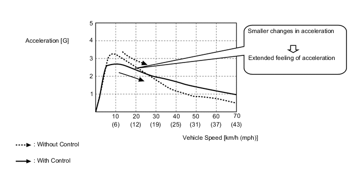
In conventional control, the characteristics of the driving torque depend on the accelerator pedal angle (throttle valve opening angle) and the variable gear range selected. However, allowing free play for engine torque in each variable gear range enables the transmission to make utmost use of the engine torque in each gear range, reducing the frequency of automatic downshifts. Additionally, changes in acceleration are made smaller compared to the increase in vehicle speed, realizing an extended feeling of acceleration which does not rely on the variable gear range.
Figure 1. Motive Force Characteristics
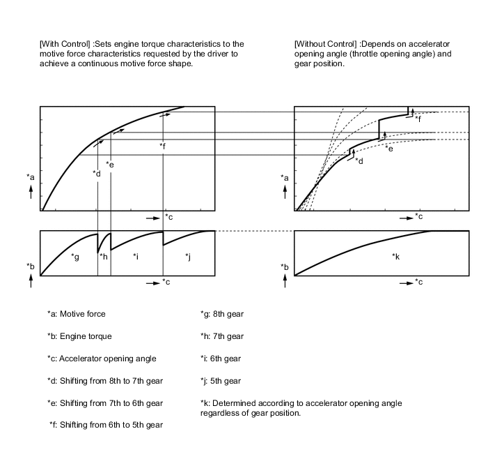
Figure 2. Acceleration when Accelerator Pedal Opening Angle is Maintained at Certain Amount
-
-
-
Deceleration Downshift Control
-
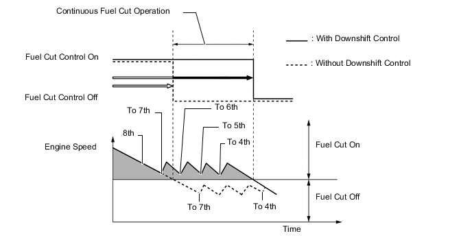
The ECM performs downshift control to help prevent the engine speed from decreasing, thus keeping fuel cut control operating for as long as possible. In this way, fuel economy is improved.
-
In this control, the transmission downshifts from 7th to 4th before fuel cut control ends when the vehicle is decelerated in the 8th gear, so that fuel cut control continues operating.
-
-
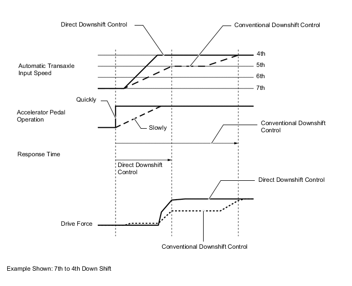
Direct Downshift Control
-
For conventional downshift control, when shifting 7th to 4th, downshifts use an intermediate gear, in order to achieve smooth acceleration response. In addition to conventional control, direct downshift control is used for this vehicle. This control skips unnecessary shifts, enabling the vehicle to downshift directly from 7th to 4th.
-
When the accelerator pedal is depressed quickly, direct downshift control enables direct downshifts with a quick shift response, skipping unnecessary shifts. Direct downshift control places the emphasis on reducing the time required to achieve the target gear. Conventional downshift control is used when the accelerator pedal is depressed slowly, providing smooth acceleration response. As a result, this logic achieves downshift responsiveness in accordance with the driver's intentions.
-
-
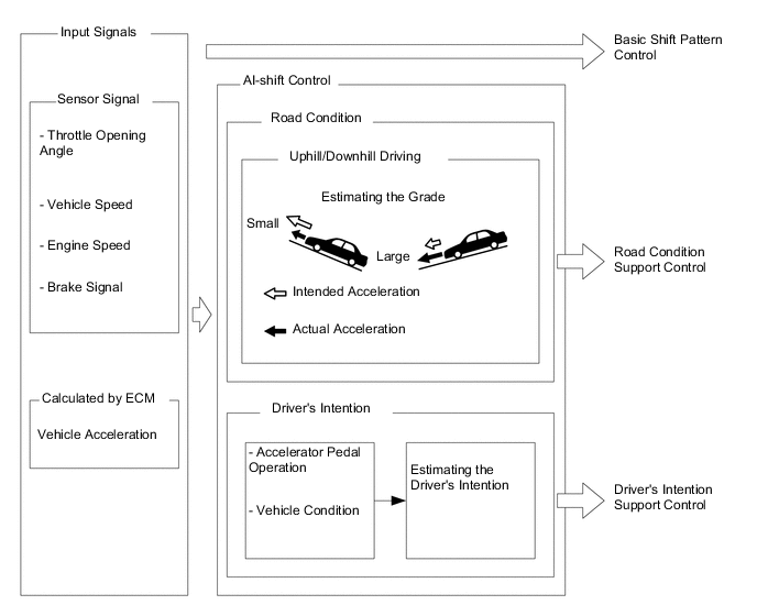
Artificial Intelligence Shift Control (AI-shift Control)
-
The automatic transaxle gear is determined by the shift pattern, which uses the vehicle speed and throttle valve opening angle.
-
Additionally, AI-shift control enables the ECM to estimate the road conditions and the driver's intention in order to automatically control the shift pattern in the manner. As a result, a comfortable ride has been achieved.
-
AI-shift control includes road condition support control and driver's intention support control.
-
AI-shift control determines transaxle control based on input signals and automatically changes the shift pattern.
-
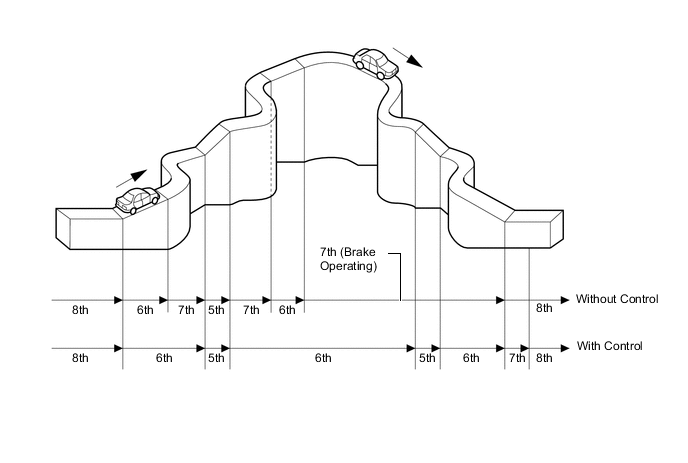
Under road condition support control, the ECM determines the throttle opening angle and the vehicle speed in addition to whether the vehicle is being driven uphill or downhill. To achieve the drive force while driving uphill, this control prevents unnecessary upshifts. To achieve engine braking while driving downhill, this control automatically performs downshifts.
-
The ECM estimates the driver's intention based on the accelerator operation and vehicle operating conditions to select a shift pattern that is well-suited to each driver, without the need to operate the shift pattern select switch used on conventional models.
-
-
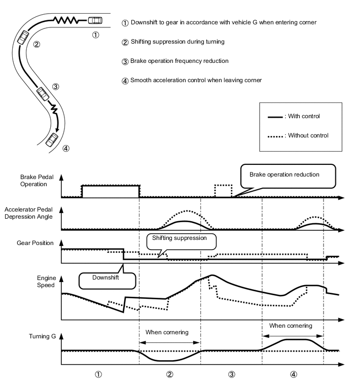
G AI-shift Control
-
When the shift lever is in D, and the drive mode switches to SPORT mode*1 or SPORT S/S+ mode*2, the vehicle condition when entering a corner is comprehensively determined according to the acceleration rate in the vehicle's longitudinal and lateral directions and driver operations. As a result, downshift to the optimal shift position is performed. Furthermore, the gear position is held during turning to provide powerful acceleration when leaving the corner, making smooth acceleration control possible.
*1: Models without adaptive variable suspension system
*2: Models with adaptive variable suspension system
-
-
Multi-mode Automatic Transmission
-
When the shift lever is moved to M, the system changes from automatic shift control to M mode control, where the driver can manually change the gear position by moving the shift lever to the "+" (upshift) and "-" (downshift) sides.
-
-
M Mode Control
-
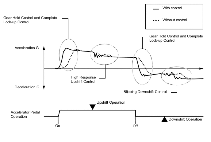
When the shift lever is in M, the gear hold control, complete lock-up control, high response upshift control and blipping downshift control are used in order to improve response in accordance with the driver's operation of the accelerator pedal, shift lever, and to improve gear shift feeling.
-
An easy drive function is used to downshift to a gear position selected according to the vehicle speed to make driving with powerful acceleration possible when a kick down operation (the accelerator pedal is depressed once, and then depressed further by the driver) is performed and the kick down switch is turned on.
-
Gear Hold Control
-
Gear shifting will not be performed under gear hold control as long as the shift lever is not operated. This makes it possible to make efficient use of the highest engine speeds. However, in the following cases, operation of gear hold control is limited.
-
When the accelerator pedal is fully depressed and a kick down operation is performed, a downshift to a gear position determined according to the vehicle speed is performed.
-
When the vehicle speed and engine speed decrease, a downshift is performed.
-
When the engine speed reaches the red zone, an automatic upshift is performed.
-
When the ATF temperature is high, gear shifting will be performed automatically.
-
When the ATF or engine coolant temperature is low, gear shifting will be performed automatically.
-
-
Complete Lock-up Control
-
While the shift lever is in M, lock-up control operates from 3rd gear, transmitting the changes in engine power directly to the output shaft, the same way as with a manual transmission. As a result, direct response to the accelerator operation is achieved. However, lock-up is not performed and the torque converter function operates at its fullest during 1st or 2nd gear selection or when in 3rd gear or higher in the low engine speed range.
Complete Lock-up Operation Gear Position Shift Range M8 M7 M6 M5 M4 M3 M2 1st - - - - - - - 2nd - - - - - - ○ 3rd - - - - - ○ - 4th - - - - ○ - - 5th - - - ○ - - - 6th - - ○ - - - - 7th - ○ - - - - - 8th ○ - - - - - - ○: Operates
-: Not applicable
-
-
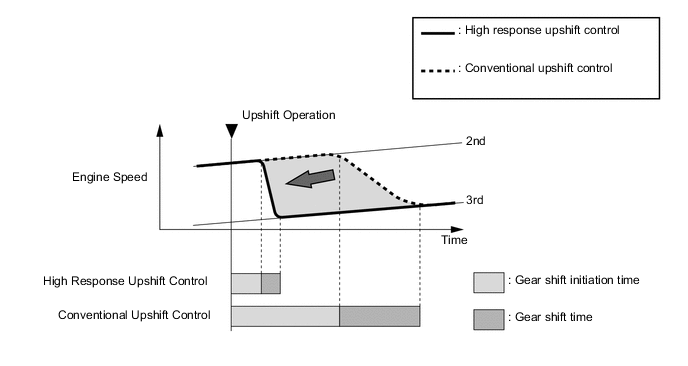
High Response Upshift Control
-
The high response upshift control achieves highly responsive upshift operation using clutch to clutch pressure control, which regulates each clutch and brake quickly and precisely, and by using the powertrain cooperative control, which optimally regulates engine torque during shifting.
-
The high response upshift control activates when the shift lever is in M.
-
Engine torque reduction via engine integrated control is precisely controlled to the optimal state according to the driving conditions from the fuel cut to normal control.
Figure 3. Upshift from 2nd to 3rd Gear
-
-
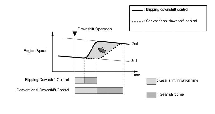
Blipping Downshift Control
-
The blipping downshift control regulates each clutch and brake using the clutch to clutch pressure control, allowing them to be engaged smoothly and disengaged quickly. In addition, fuel injection volume is increased and engine speed is boosted by the powertrain cooperative control, thus ensuring proper engine brake force. In this way, a smooth and quick downshift is achieved.
-
The blipping downshift control activates by downshifting with the shift lever in D or M.
Figure 4. Downshift from 3rd to 2nd Gear
-
-
-
-
FUNCTION
-
Drive Mode Select
-
The motive force characteristics for the accelerator opening angle can be changed through the selection of the drive mode according to driver preference.
-
The drive mode can be switched by turning the dial type drive mode select. In addition, the vehicle can be returned to NORMAL mode by pressing the drive mode select.
-
An indicator is provided in the combination meter assembly and the drive mode the driver selected can be recognized.
Figure 5. LHD Models
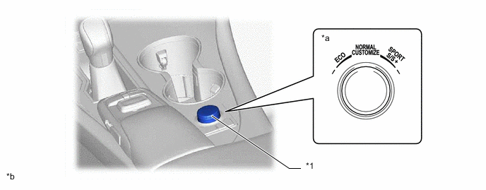
*1 Integration Control and Panel Assembly - - *a Drive Mode Select *b This illustration is an example. Figure 6. RHD Models
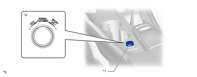
*1 Combination Switch Assembly - - *a Drive Mode Select *b This illustration is an example. Characteristics of Drive Mode Drive Mode Characteristics NORMAL Mode This drive mode provides optimum driveability. ECO Mode The ECM optimizes fuel economy and driving performance by gradually generating the motive force in comparison to the accelerator pedal operation. At the same time, the ECM supports eco driving by optimizing air conditioning performance. SPORT Mode*1
SPORT S/S+ Mode*2
The ECM controls motive force in the intermediate area of the accelerator pedal opening to a greater degree than that of NORMAL mode, improving acceleration performance. In addition, engine speed response performance has been improved in the high area of the accelerator pedal opening, thus producing a sporty drive. *1: Models without adaptive variable suspension system
*2: Models with adaptive variable suspension system
-
-
Gear Shift Indicator (Models for Europe Excluding Package Model Options for Russia)
-
Gear Shift Indicator is a system to promote upshifting to the fuel-efficient and optimal gear position in accordance with the driving conditions such as the accelerator pedal opening amount and the vehicle speed, etc. when the vehicle is being driven while the shift lever is in M.
-
By driving in accordance with the upshifting recommendations indicated by the Gear Shift Indicator in the combination meter assembly, the driver can enhance environmental performance, improve fuel economy and reduce exhaust gas output within the limits of engine performance.
-
-
-
FAIL-SAFE
-
The fail-safe function minimizes the loss of operability when an abnormality occurs in a sensor or a shift solenoid valve.
-
For details, refer to the Repair Manual.
-
-
DIAGNOSIS
-
When the ECM detects a malfunction, the ECM records the malfunction and memorizes the information related to the fault. Furthermore, the ECM illuminates the Malfunction Indicator Lamp (MIL) in the combination meter to inform the driver.
-
The ECM will also store Diagnostic Trouble Codes (DTCs) of the malfunctions. The DTCs stored in the ECM are output to the Global TechStream (GTS) via the DLC3.
-
For details, refer to the Repair Manual.
-