GENERATOR(for 100A Type) DISASSEMBLY
PROCEDURE
REMOVE GENERATOR PULLEY CAP
-
*1
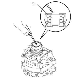
Generator Pulley Cap
Using a screwdriver, remove the generator pulley cap.
-
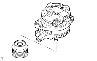
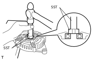
REMOVE GENERATOR WITH CLUTCH PULLEY
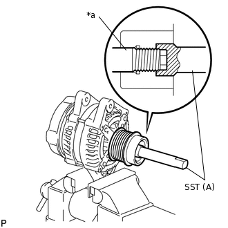
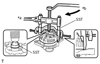
Secure the generator drive end frame in a vise between aluminum plates.
-
*a
Rotor Shaft
Place the rotor shaft end into SST (A).
09820-63021
-
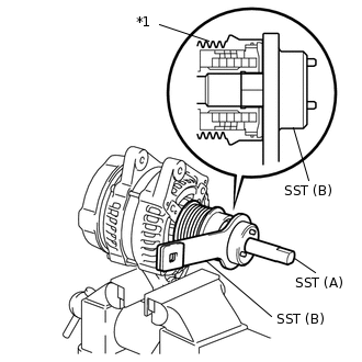
*1
Generator with Clutch Pulley
Fit SST (B) to the generator with clutch pulley.
Note:Securely attach SST to the generator with clutch pulley and rotor shaft.
-
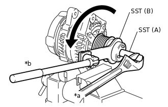
*a
Hold
*b
Turn
Loosen the generator with clutch pulley by turning SST (B) as shown in the illustration.
Note:Check that the generator drive end frame is secured in the vise tightly.
Hold SST (A) tightly during the operation.
Remove SST from the generator with clutch pulley.
Remove the generator with clutch pulley from the rotor shaft.
Remove the generator assembly from the vise.
REMOVE GENERATOR REAR END COVER
-
Place the generator assembly on the generator with clutch pulley.
-
Remove the 3 bolts and generator rear end cover from the generator coil assembly.
-
REMOVE GENERATOR TERMINAL INSULATOR
-
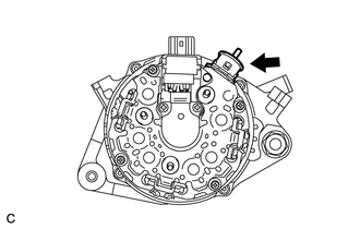
Remove the generator terminal insulator from the generator coil assembly.
-
REMOVE GENERATOR BRUSH HOLDER ASSEMBLY
-
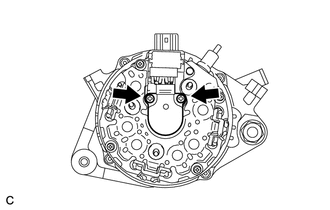
Remove the 2 screws and generator brush holder assembly from the generator coil assembly.
-
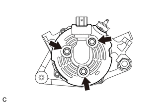
REMOVE GENERATOR COIL ASSEMBLY
-
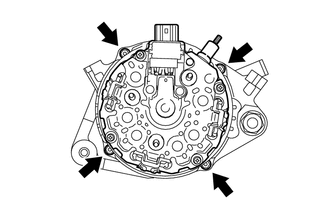
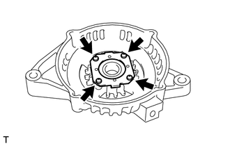
Remove the 4 bolts.
-
*a
Hold
*b
Turn
Using SST, remove the generator coil assembly.
09950-40011
09951-04020
09952-04010
09953-04020
09954-04010
09955-04071
09957-04010
09958-04011
-
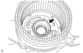
Remove the bearing cover packing.
Note:If the bearing cover packing breaks, remove broken pieces completely.
Tip:The bearing cover packing may be installed on the generator rotor assembly.
-
REMOVE GENERATOR ROTOR ASSEMBLY
-
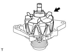
Remove the generator rotor assembly from the generator drive end frame.
Note:Do not drop the generator rotor assembly.
-
REMOVE GENERATOR DRIVE END FRAME BEARING
-
Remove the 4 screws and retainer plate from the generator drive end frame.
-
Using SST and a hammer, tap out the generator drive end frame bearing from the generator drive end frame.
09950-60010
09951-00250
09950-70010
09951-07100
-