WHEN REMOVING,INSTALLING,REPAIRING OR REPLACING PARTS WHEEL ALIGNMENT STANDARD
-
MEASURE VEHICLE HEIGHT
-
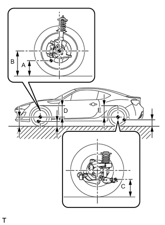
Bounce the vehicle up and down at the corners to stabilize the suspension before inspecting the vehicle height.
Vehicle Height (Unloaded Vehicle) Tire Size Front B - A Rear C Front D Rear E 205/55 R16 146 mm
(5.75 in.)
225 mm
(8.86 in.)
375 mm
(14.76 in.)
372 mm
(14.65 in.)
215/45 R17 146 mm
(5.75 in.)
225 mm
(8.86 in.)
375 mm
(14.76 in.)
372 mm
(14.65 in.)
Note
-
Perform the inspection while the vehicle is empty (with a spare tire, jack and tools on board, and with the fuel tank filled with fuel).
-
The standard value shown here is a value that is used for adjusting the wheel alignment and does not indicate the height of an actual vehicle.
-
-
-
INSPECT CAMBER, CASTER AND STEERING AXIS INCLINATION
Note
Perform the inspection while the vehicle is empty (without a spare tire, jack or tools on board, but with the fuel tank filled with fuel).
-
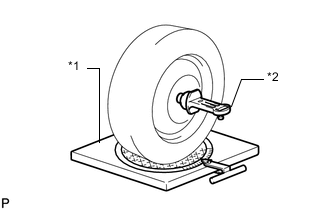
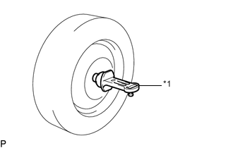
Text in Illustration *1 Alignment tester *2 Camber-Caster-Steering Axis Inclination Gauge Put the front wheel on the center of the alignment tester.
-
Remove the wheel cap.
-
Set the camber-caster-steering axis inclination gauge at the center of the axle hub or drive shaft.
-
Inspect the camber, caster and steering axis inclination.
Note
-
Perform the inspection while the vehicle is empty (with a spare tire, jack and tools on board, and with the fuel tank filled with fuel).
-
The tolerance for the difference between the left and right wheels is 45' (0.75°) or less for both the camber.
-
-
Remove the camber-caster-steering axis inclination gauge and attachment.
-
Install the wheel cap.
If the caster and steering axis inclination are not within the specified values after the camber has been correctly adjusted, recheck the suspension parts for damage and wear.
-
-
INSPECT TOE-IN (FRONT)
-
Bounce the vehicle up and down at the corners to stabilize the suspension.
-
Release the parking brake and move the shift lever to the neutral position (for manual transmission).
-
Release the parking brake and move the shift lever to N (for Automatic transmission).
-
Push the vehicle straight ahead approximately 5 m (16.4 ft.). (Step A)
-
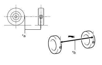
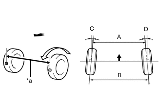
Text in Illustration *a Tread Center Mark *b Dimension B 
Front of the Vehicle Put tread center marks on the rearmost points of the front wheels and measure the distance between the marks (dimension B).
-
Slowly push the vehicle straight ahead to cause the front wheels to rotate 180°. Use the front tire valve as a reference point.
Tech Tips
Do not allow the wheels to rotate more than 180°. If the wheels rotate more than 180°, perform the procedure from Step A again.
-

Text in Illustration *a Dimension A Front of the Vehicle Measure the distance between the tread center marks on the front side of the wheels (dimension A).
Tech Tips
Measure "B - A" only when "C + D" cannot be measured.
If the toe-in is not within the specified value, adjust it at the rack ends.
-
-
INSPECT WHEEL ANGLE
-
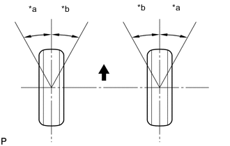
Text in Illustration *a Inside *b Outside Front of the Vehicle Put tread center marks on the rearmost points of a turning radius gauge.
-
Turn the steering wheel fully to the left and right and measure the turning angle.
Tech Tips
Inspect while the vehicle is unloaded.
-
-
INSPECT TOE-IN (REAR)
Note
Inspect while the vehicle is unloaded.
-
Bounce the vehicle up and down at the corners to stabilize the suspension.
-
Release the parking brake and move the shift lever to N.
-
Push the vehicle straight ahead approximately 5 m (16.4 ft.). (Step B)
-

Text in Illustration *a Tread Center Mark *b Dimension B Front of the Vehicle Put tread center marks on the rearmost points of the rear wheels and measure the distance between the marks (dimension B).
-
Slowly push the vehicle straight ahead to cause the rear wheels to rotate 180°. Use the rear tire valve as a reference point.
Tech Tips
Do not allow the wheels to rotate more than 180°. If the wheels rotate more than 180°, perform the procedure from Step B again.
-
Text in Illustration *a Dimension A Front of the Vehicle Measure the distance between the tread center marks on the front of the rear wheels (dimension A).
Tech Tips
Measure "B - A" only when "C + D" cannot be measured.
If the toe-in is not within the specified range, adjust it at the toe control link sub-assembly.
-
-
INSPECT CAMBER (REAR)
-
Remove the center wheel ornament.
-
Text in Illustration *1 Camber-caster-kingpin Gauge Install a camber-caster-kingpin gauge at the center of the axle hub or drive shaft.
-
Inspect the camber.
If the measured value is not within the specified range, inspect the suspension parts for damage and wear. Replace parts as necessary because camber cannot be properly adjusted with any damaged or worn parts.
-
Remove the camber-caster-kingpin gauge.
-
Install the center wheel ornament.
-
-
INSPECT REAR SUSPENSION
-
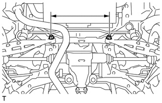
Inspect the rear suspension member.
-
Measure the distance between the centers of the 2 installation bolts of the rear No. 2 suspension arm assembly LH and RH
If the distance is not within the specified range, replace the rear suspension member.
-
-
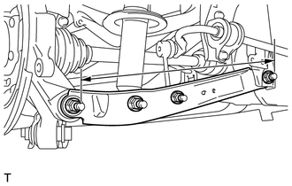
Inspect the rear No. 2 suspension arm assembly.
-
Measure the distance between the centers of the 2 installation bolts of the rear No. 2 suspension arm assembly.
If the distance is not within the specified range, replace the rear No. 2 suspension arm assembly.
-
-
Inspect and adjust the toe-in and camber.
-
Inspect the toe-in and camber.
Inspect the toe-in and camber. If the values are not within the specified ranges, adjust the installation bolt holding the rear suspension member to the vehicle body, or the bolt holding the upper control arm and rear suspension arm so that the values fall within the specified ranges.
-
-