AIR CONDITIONING SYSTEM (for Automatic Air Conditioning System), Diagnostic DTC:14
| DTC Code | DTC Name |
|---|---|
| 14 | Engine Coolant Temperature Communication Circuit |
DESCRIPTION
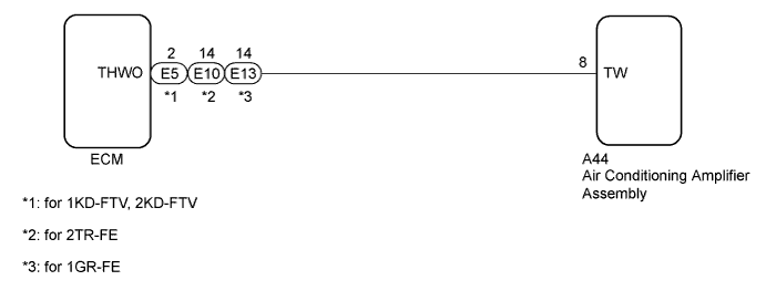
The engine coolant temperature sensor connected to the ECM detects the engine coolant temperature, which is used for warm up control when the engine is cold. The engine coolant temperature sensor sends a signal to the air conditioning amplifier assembly via the ECM.
| DTC Code | DTC Detection Condition | Trouble Area |
|---|---|---|
| 14 | An open or short in engine coolant temperature communication circuit |
|
WIRING DIAGRAM
INSPECTION PROCEDURE
PROCEDURE
-
CHECK ENGINE TYPE
-
Check the engine type.
Result Result Proceed to Engine type: 1GR-FE A Engine type: 1KD-FTV B Engine type: 2KD-FTV C Engine type: 2TR-FE D
B 
CHECK FOR DTC (ENGINE CONTROL SYSTEM) Click here
C
CHECK FOR DTC (ENGINE CONTROL SYSTEM) Click here
D
CHECK FOR DTC (ENGINE CONTROL SYSTEM) Click here
A 
-
-
CHECK FOR DTC (ENGINE CONTROL SYSTEM)
-
Clear the DTCs Click here.
-
Check the DTC Click here.
Result Result Proceed to DTC (P0115, P0117 or P0118) is not output. A DTC (P0115, P0117 or P0118) is output. B
B 
GO TO SFI SYSTEM Click here
A
-
-
CHECK HARNESS AND CONNECTOR (AIR CONDITIONING AMPLIFIER - ECM)
-
Disconnect the A44 air conditioning amplifier assembly connector.
-
Disconnect the E13 ECM connector.
-
Measure the resistance according to the value(s) in the table below.
Standard Resistance Tester Connection Condition Specified Condition A44-8 (TW) - E13-14 (THWO) Always Below 1 Ω A44-8 (TW) - Body ground Always 10 kΩ or higher Result Result Proceed to OK (When troubleshooting according to problem symptoms table.) A OK (When troubleshooting according to DTC.) B NG C
B
REPLACE AIR CONDITIONING AMPLIFIER ASSEMBLY Click here
C
REPAIR OR REPLACE HARNESS OR CONNECTOR
A 
PROCEED TO NEXT SUSPECTED AREA SHOWN IN PROBLEM SYMPTOMS TABLE Click here
-
-
CHECK FOR DTC (ENGINE CONTROL SYSTEM)
-
Clear the DTCs.
-
for DPF: Click here.
-
w/ EGR Cooler: Click here.
-
w/o EGR Cooler: Click here.
-
-
Check the DTC.
-
for DPF: Click here.
-
w/ EGR Cooler: Click here.
-
w/o EGR Cooler: Click here.
Result Result Proceed to DTC (P0115, P0117 or P0118) is not output. A DTC (P0115, P0117 or P0118) is output. (for DPF) B DTC (P0115, P0117 or P0118) is output. (w/ EGR Cooler) C DTC (P0115, P0117 or P0118) is output. (w/o EGR Cooler) D -
B
GO TO ECD SYSTEM Click here
C
GO TO ECD SYSTEM Click here
D
GO TO ECD SYSTEM Click here
A
-
-
CHECK HARNESS AND CONNECTOR (AIR CONDITIONING AMPLIFIER - ECM)
-
Disconnect the A44 air conditioning amplifier assembly connector.
-
Disconnect the E5 ECM connector.
-
Measure the resistance according to the value(s) in the table below.
Standard Resistance Tester Connection Condition Specified Condition A44-8 (TW) - E5-2 (THWO) Always Below 1 Ω A44-8 (TW) - Body ground Always 10 kΩ or higher Result Result Proceed to OK (When troubleshooting according to problem symptoms table.) A OK (When troubleshooting according to DTC.) B NG C
B
REPLACE AIR CONDITIONING AMPLIFIER ASSEMBLY Click here
C
REPAIR OR REPLACE HARNESS OR CONNECTOR
A
PROCEED TO NEXT SUSPECTED AREA SHOWN IN PROBLEM SYMPTOMS TABLE Click here
-
-
CHECK FOR DTC (ENGINE CONTROL SYSTEM)
-
Clear the DTCs Click here.
-
Check the DTC Click here.
Result Result Proceed to DTC (P0115, P0117 or P0118) is not output. A DTC (P0115, P0117 or P0118) is output. B
B
GO TO SFI SYSTEM Click here
A
-
-
CHECK HARNESS AND CONNECTOR (AIR CONDITIONING AMPLIFIER - ECM)
-
Disconnect the A44 air conditioning amplifier assembly connector.
-
Disconnect the E10 ECM connector.
-
Measure the resistance according to the value(s) in the table below.
Standard Resistance Tester Connection Condition Specified Condition A44-8 (TW) - E10-14 (THWO) Always Below 1 Ω A44-8 (TW) - Body ground Always 10 kΩ or higher Result Result Proceed to OK (When troubleshooting according to problem symptoms table.) A OK (When troubleshooting according to DTC.) B NG C
B
REPLACE AIR CONDITIONING AMPLIFIER ASSEMBLY Click here
C
REPAIR OR REPLACE HARNESS OR CONNECTOR
A
PROCEED TO NEXT SUSPECTED AREA SHOWN IN PROBLEM SYMPTOMS TABLE Click here
-