ENGINE UNIT INSPECTION
-
CLEAN CYLINDER BLOCK SUB-ASSEMBLY
-
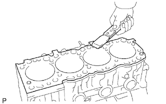
Using a gasket scraper, remove all the gasket material from the top surface of the cylinder block.
-
Using a soft brush and solvent, thoroughly clean the cylinder block.
-
-
INSPECT CYLINDER BLOCK SUB-ASSEMBLY
-
Inspect for flatness.
-
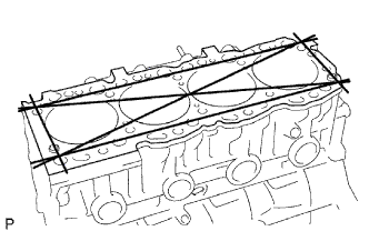
Using a precision straightedge and feeler gauge, measure the surfaces contacting the cylinder head and main bearing cap for warpage.
Maximum warpage 0.20 mm (0.0079 in.) If the warpage is greater than the maximum, replace the cylinder block.
-
-
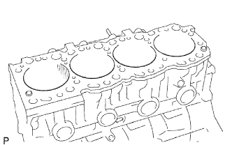
Visually check the cylinder for vertical scratches. If deep scratches are present, rebore all 4 cylinders . If necessary, replace the cylinder block.
-
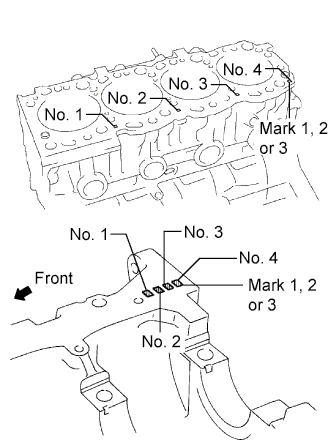
Inspect the cylinder bore diameter.
Tech Tips
There are 3 sizes of the standard cylinder bore diameter, marked "1", "2" and "3" accordingly. The mark is stamped on the lower left rear of the cylinder block.
-
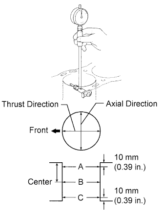
Using a cylinder gauge, measure the cylinder bore diameter at positions A, B and C in the thrust and axial directions.
Standard diameter Number Mark Specified Condition Mark 1 99.500 to 99.510 mm (3.9173 to 3.9177 in.) Mark 2 99.510 to 99.520 mm (3.9177 to 3.9181 in.) Mark 3 99.520 to 99.530 mm (3.9181 to 3.9185 in.) Maximum diameter Item Specified Condition STD 99.73 mm (3.9264 in.) O/S 0.50 100.23 mm (3.9461 in.) If the diameter is greater than the maximum, rebore all the 4 cylinders. If necessary, replace the cylinder block.
-
-
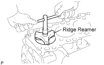
Remove the cylinder ridge.
If the wear is less than 0.2 mm (0.008 in.), using a ridge reamer, grind the top of the cylinder.
-
-
CLEAN PISTON SUB-ASSEMBLY WITH PIN
-
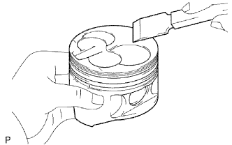
Using a gasket scraper, remove the carbon from the piston top.
-
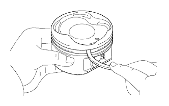
Using a groove cleaning tool or broken ring, clean the piston ring grooves.
-
Using solvent and a brush, thoroughly clean the piston.
Note
Do not use a wire brush.
-
-
INSPECT PISTON SUB-ASSEMBLY
-
Inspect the piston oil clearance.
Tech Tips
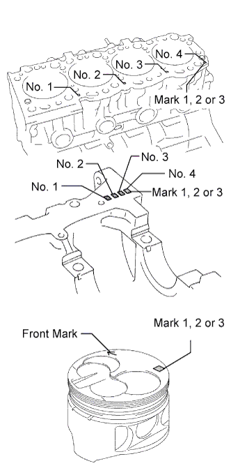
There are 3 sizes of the standard piston diameter, marked "1", "2" and "3" accordingly. The mark is stamped on the piston top.
-
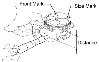
Using a micrometer, measure the piston diameter at right angles to the piston center line where the distance from the piston head is as specified.
Distance 61.27 to 61.33 mm (2.4122 to 2.4146 in.) Standard piston diameter Number Mark Specified Condition Mark 1 99.450 to 99.460 mm (3.9153 to 3.9157 in.) Mark 2 99.460 to 99.470 mm (3.9157 to 3.9161 in.) Mark 3 99.470 to 99.480 mm (3.9161 to 3.9165 in.) O/S 0.50 99.950 to 99.980 mm (3.9350 to 3.9362 in.) -
Measure the cylinder bore diameter in the thrust directions.
-
Subtract the piston diameter measurement from the cylinder bore diameter measurement.
Standard oil clearance 0.090 to 0.111 mm (0.0035 to 0.0044 in.) Maximum oil clearance 0.13 mm (0.0051 in.) If the oil clearance is greater than the maximum, replace all the 4 pistons and rebore all the 4 cylinders. If necessary, replace the cylinder block.
Tech Tips
Use a piston with the same number mark as the cylinder diameter marked on the cylinder block.
-
-
Inspect the piston pin fit.
-
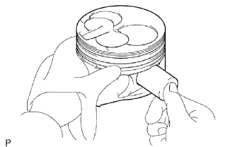
Heat the piston to approximately. 60°C (140°F), and push the piston pin into the piston pin hole with your thumb.
If the pin can be installed at a lower temperature, replace the piston and pin as a set.
-
-
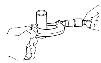
Using a micrometer, measure the piston pin diameter.
Standard piston pin diameter 29.000 to 29.012 mm (1.1417 to 1.1422 in.)
-
-
INSPECT PISTON RING SET
-
Inspect the piston ring groove clearance.
-
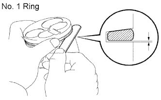
No. 1 ring:
Install a new piston ring to the piston. Using a feeler gauge, measure the clearance between the piston ring and the wall of the ring groove.
Standard groove clearance 0.057 to 0.101 mm (0.0022 to 0.0040 in.) Maximum groove clearance 0.20 mm (0.0079 in.) If the clearance is greater than the maximum, replace the piston.
-
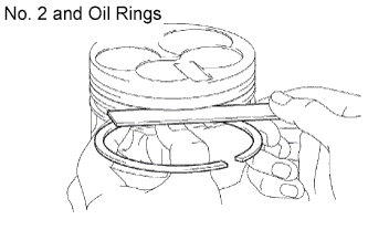
No. 2 and oil rings:
Using a feeler gauge, measure the clearance between a new piston ring and the wall of the ring groove.
Standard groove clearance Item Specified Condition No. 2 piston ring 0.060 to 0.100 mm (0.0024 to 0.0039 in.) Oil ring 0.030 to 0.070 mm (0.0012 to 0.0028 in.) Maximum groove clearance 0.20 mm (0.0079 in.) If the clearance is greater than the maximum, replace the piston.
-
-
Inspect the piston ring end gap.
-
Insert the piston ring into the cylinder bore.
-
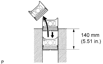
Using a piston, push the piston ring a little beyond the bottom of the ring travel, 140 mm (5.15 in.) from the top of the cylinder block.
-
Using a feeler gauge, measure the end gap.
Standard end gap Item Specified Condition No. 1 piston ring 0.350 to 0.590 mm (0.0138 to 0.0232 in.) No. 2 piston ring 0.470 to 0.720 mm (0.0185 to 0.0283 in.) Oil ring 0.200 to 0.520 mm (0.0079 to 0.0205 in.) Maximum end gap Item Specified Condition No. 1 piston ring 1.29 mm (0.0508 in.) No. 2 piston ring 1.42 mm (0.0559 in.) Oil ring 1.22 mm (0.0480 in.) If the end gap is greater than the maximum, replace the piston ring.
If the end gap is greater than the maximum even with a new piston ring, rebore all 4 cylinders or replace the cylinder block.
-
-
-
INSPECT CONNECTING ROD SUB-ASSEMBLY
-
Using a rod aligner and feeler gauge, check the connecting rod alignment.
-
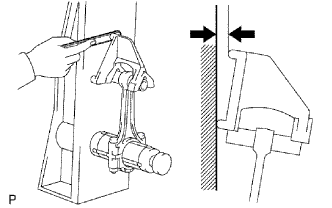
Check if the connecting rod is bent.
Maximum bend 0.05 mm (0.0020 in.) per 100 mm (3.94 in.) If the bend is greater than the maximum, replace the connecting rod.
-
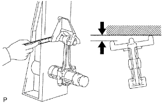
Check if the connecting rod is twisted.
Maximum twist 0.15 mm (0.0059 in.) per 100 mm (3.94 in.) If the twist is greater than the maximum, replace the connecting rod.
-
-
-
INSPECT PISTON PIN OIL CLEARANCE
-
Inspect the piston pin oil clearance.
-
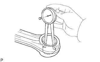
Using a caliper gauge, measure the inside diameter of the connecting rod bush.
Standard bush inside diameter 29.008 to 29.020 mm (1.1420 to 1.1425 in.) -
Subtract the piston pin diameter measurement from the bush inside diameter measurement.
Standard oil clearance 0.004 to 0.012 mm (0.0002 to 0.0005 in.) Maximum oil clearance 0.05 mm (0.0020 in.) If the oil clearance is greater than the maximum, replace the bush.
If necessary, replace the piston and piston pin with a new piston and pin set.
-
-
-
INSPECT CONNECTING ROD BOLT
-
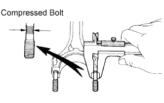
Using a vernier caliper, measure the tension portion of the connecting rod bolt.
Standard diameter 8.400 to 8.600 mm (0.3307 to 0.3386 in.) Minimum diameter 8.20 mm (0.3228 in.) If the diameter is less than the minimum, replace the bolt.
-
-
INSPECT CRANKSHAFT
-
Inspect for circle runout.
-
Place the crankshaft on V-blocks.
-
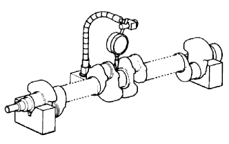
Using a dial indicator, measure the circle runout at the center journal.
Maximum circle runout 0.06 mm (0.0024 in.) If the circle runout is greater the maximum, replace the crankshaft.
-
-
Inspect the main journals and crank pins.
-
Using a micrometer, measure the diameter of each main journal and crank pin.
Main journal diameter Size Specified Condition STD 61.985 to 62.000 mm (2.4403 to 2.4409 in.) U/S 0.25 61.745 to 61.755 mm (2.4309 to 2.4313 in.) U/S 0.50 61.495 to 61.505 mm (2.4211 to 2.4215 in.) Crank pin diameter Size Specified Condition STD 54.988 to 55.000 mm (2.1649 to 2.1654 in.) U/S 0.25 54.745 to 54.755 mm (2.1553 to 2.1557 in.) U/S 0.50 54.495 to 54.505 mm (2.1455 to 2.1459 in.) If the diameter is not as specified, check the oil clearance. If necessary, replace the crankshaft.
-
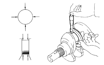
Check each main journal and crank pin for taper and out of round as shown in the illustration.
Maximum taper and out of round 0.02 mm (0.0008 in.) If the taper and out of round is greater than the maximum, replace the crankshaft.
-
-
If necessary, grind and hone the main journals and/or crank pins.
-
Grind and hone the main journals and/or crank pins to the finished undersized diameter.
-
Install new main journal and/or crankshaft pin undersized bearing.
-
-
-
INSPECT NO. 1 OIL NOZZLE
-
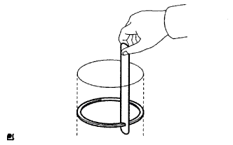
Inspect the check valve
-
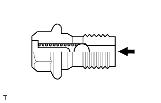
Push the valve with a wooden stick to check if it is stuck.
If stuck, replace the check valve.
-
-
Inspect the oil nozzle
-
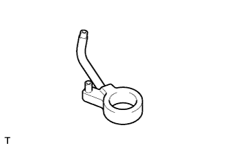
Check the oil nozzle for damage or clogging.
If necessary, replace the oil nozzle.
-
-