CAMSHAFT (for Bank 2) INSTALLATION
-
INSTALL NO. 3 CAMSHAFT
Note
As the thrust clearance of the camshaft is small, the camshaft must be kept level while it is being installed. If the camshaft is not kept level, the portion of the cylinder head which receives the shaft thrust may crack or be damaged, causing the camshaft to seize or break. To avoid this, the following steps should be carried out.
-
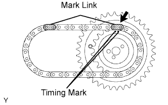
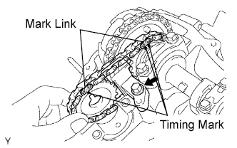
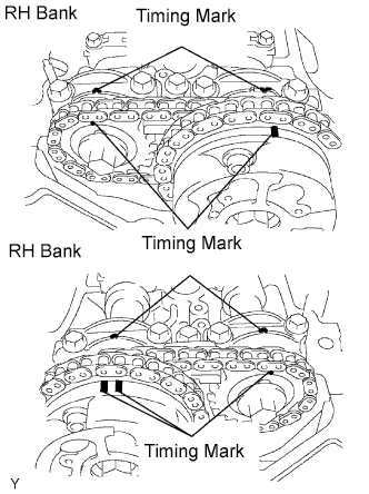
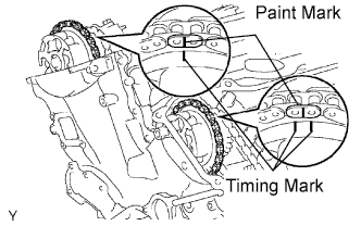
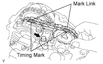
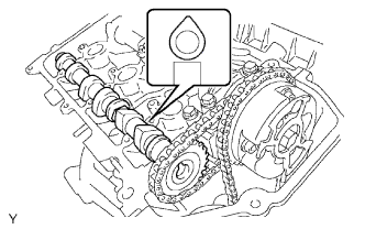
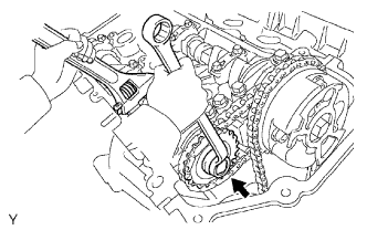
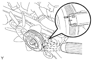
Align the mark link (yellow) with the timing mark (2 dot marks) of the camshaft timing gear as shown in the illustration.
-
Apply new engine oil to the thrust portion and journal of the camshafts.
-
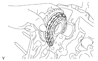
Temporarily put the No. 1 chain on the No. 2 chain of the camshaft timing gear.
-
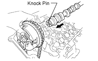
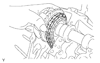
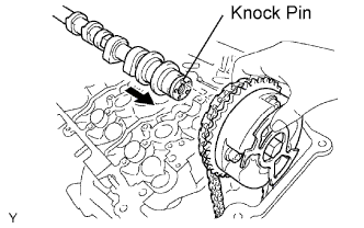
Align the knock pin hole in the camshaft timing gear with the knock pin of the No. 3 camshaft, and insert the No. 3 camshaft into the camshaft timing gear.
-
Temporarily install the camshaft timing gear set bolt.
-
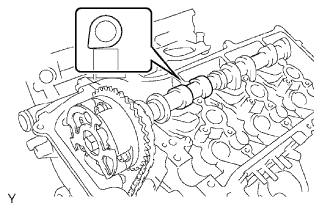
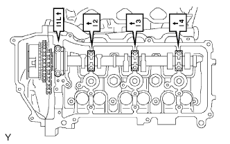
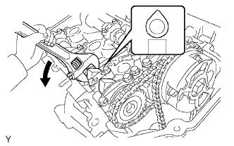
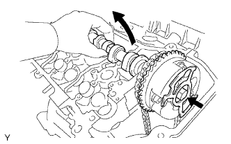
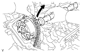
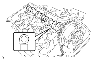
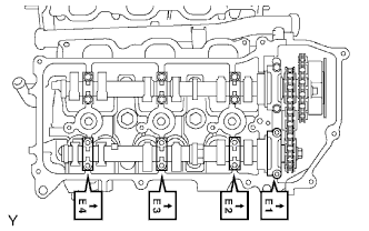
Set the No. 3 camshaft onto the LH cylinder head with the cam lobes of the No. 2 cylinder faced downward as shown in the illustration.
-
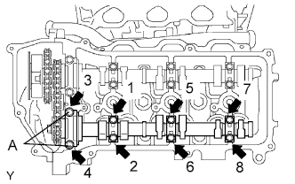
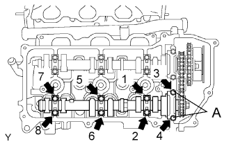
Install the 4 bearing caps in their proper locations.
-
Apply a light coat of engine oil on the threads and under the heads of the bearing cap bolts.
-
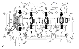
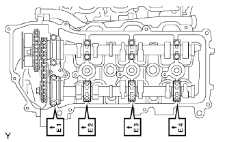
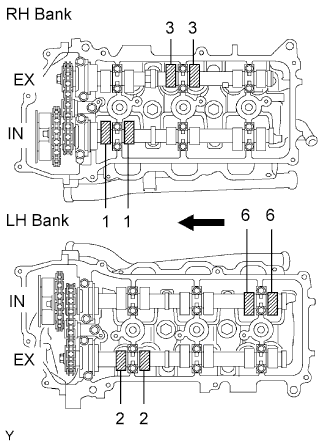
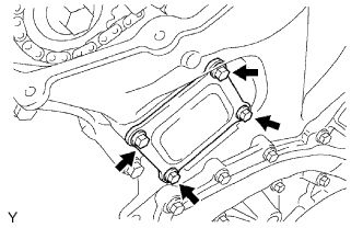
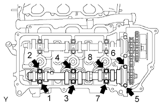
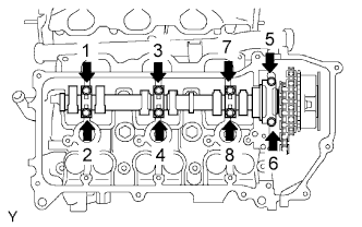
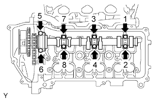
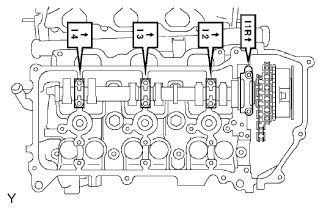
Install and uniformly tighten the 8 bearing cap bolts in several passes in the sequence shown in the illustration.
- Torque:
- 9.0 N*m { 92 kgf*cm, 80 in.*lbf, for 10 mm (0.39 in.) head }
- 24 N*m { 245 kgf*cm, 18 ft.*lbf, for 12 mm (0.47 in.) head (A) }
-
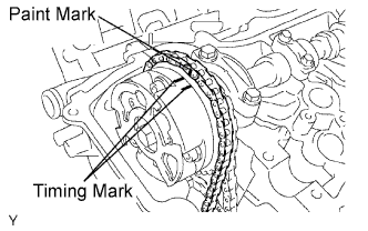
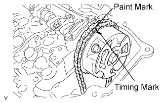
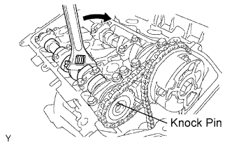
Set the paint mark of the No. 1 chain between the timing marks of the camshaft timing gear.
-
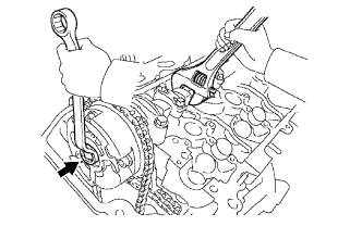
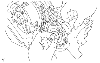
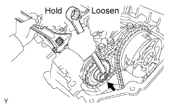
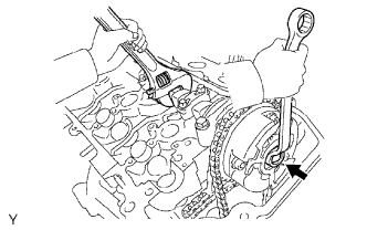
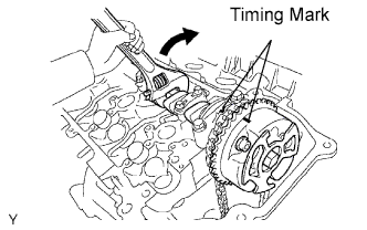
Hold the hexagonal portion of the No. 3 camshaft with a wrench, and tighten the camshaft timing gear set bolt.
- Torque:
- 100 N*m { 1,020 kgf*cm, 74 ft.*lbf }
-
-
INSTALL NO. 3 CHAIN TENSIONER
-
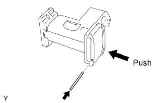
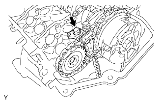
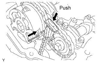
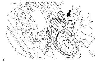
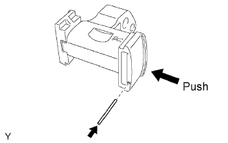
While pushing in the tensioner, insert a diameter of 1.0 mm (0.039 in.) pin into the hole to fix it in place.
-
Temporarily install the camshaft timing gear and No. 3 chain tensioner and align the mark links (yellow) with the timing marks (1 dot mark and 2 dot mark) of the camshaft timing gears.
-
Tighten the No. 3 chain tensioner bolt.
- Torque:
- 19 N*m { 194 kgf*cm, 14 ft.*lbf }
-
-
INSTALL NO. 4 CAMSHAFT
Note
As the thrust clearance of the camshaft is small, the camshaft must be kept level while it is being installed. If the camshaft is not kept level, the portion of the cylinder head which receives the shaft thrust may crack or be damaged, causing the camshaft to seize or break. To avoid this, the following steps should be carried out.
-
Align the knock pin hole in the camshaft timing gear with the knock pin of the No. 4 camshaft, and insert the No. 4 camshaft into the camshaft timing gear.
-
Temporarily install the camshaft timing gear set bolt.
-
Install the 4 bearing caps in their proper locations.
-
Apply a light coat of engine oil on the threads of the bearing cap bolts.
-
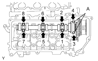
Using several steps, install and tighten the 8 bearing cap bolts uniformly in the sequence as shown in the illustration.
- Torque:
- 9.0 N*m { 92 kgf*cm, 80 in.*lbf, for 10 mm (0.39 in.) head }
- 24 N*m { 245 kgf*cm, 18 ft.*lbf, for 12 mm (0.47 in.) head (A) }
-

Hold the hexagonal portion of the No. 4 camshaft with a wrench, and tighten the camshaft timing gear set bolt.
- Torque:
- 100 N*m { 1,020 kgf*cm, 74 ft.*lbf }
-
Remove the pin from the No. 3 chain tensioner.
-
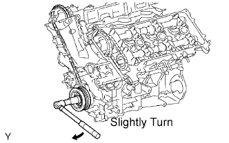
Release the chain tension between the camshaft timing gear (RH bank) and crankshaft timing gear by turning the crankshaft pulley clockwise slightly.
-
-
INSTALL NO. 1 CHAIN TENSIONER
-
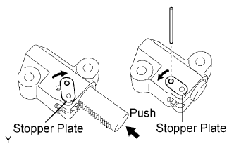
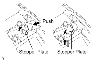
While rotating the stopper plate of the tensioner clockwise, push in the plunger of the tensioner as shown in the illustration.
-
While rotating the stopper plate of the tensioner counterclockwise, insert a bar of diameter of 3.5 mm (0.138 in.) into the holes in the stopper plate and tensioner to fix the stopper plate.
-
Install the chain tensioner with the 2 bolts.
- Torque:
- 10 N*m { 102 kgf*cm, 7 ft.*lbf }
-
-
SET NO. 1 CYLINDER TO TDC/COMPRESSION
-
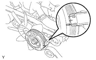
Turn the crankshaft pulley, and align its groove with the timing mark 0 of the timing chain cover.
-
Check that the timing marks of the camshaft timing gears are aligned with the timing marks of the bearing cap as shown in the illustration.
If not, turn the crankshaft 1 complete revolution (360°) and align the timing marks as above.
-
-
INSPECT VALVE CLEARANCE
-
Check the valves indicated in the illustration.
-
Using a feeler gauge, measure the clearance between the valve lifter and camshaft.
Valve clearance (Cold) Intake 0.15 to 0.25 mm (0.006 to 0.010 in.) Exhaust 0.29 to 0.39 mm (0.011 to 0.015 in.) Tech Tips
Record the out-of-specification valve clearance measurements. They will be used later to determine the required replacement valve lifter.
-
-
Turn the crankshaft 2/3 of a revolution (240°), and check the valves indicated in the illustration.
-
Using a feeler gauge, measure the clearance between the valve lifter and camshaft.
Valve clearance (Cold) Intake 0.15 to 0.25 mm (0.006 to 0.010 in.) Exhaust 0.29 to 0.39 mm (0.011 to 0.015 in.) -
Record the out-of-specification valve clearance measurements. They will be used later to determine the required replacement valve lifter.
-
-
-
ADJUST VALVE CLEARANCE
-
Set No. 1 cylinder to TDC/compression.
-
Turn the crankshaft pulley, and align the notch with the timing mark 0 of the timing chain cover.
-
Check that the timing marks of the camshaft timing gears are aligned with the timing marks of the bearing cap as shown in the illustration.
If not, turn the crankshaft 1 complete revolution (360°) and align the timing marks as above.
-
Place paint marks on the No. 1 chain links that correspond with the timing marks of the camshaft timing gears.
-
-
Remove the No. 1 chain tensioner.
Note
-
Never rotate the crankshaft with the chain tensioner removed.
-
When rotating the camshaft with the timing chain removed, turn the crankshaft counterclockwise 40° from the TDC first.
-
Remove the 4 bolts, timing chain cover plate and gasket.
-
While rotating the stopper plate of the tensioner upward, push in the plunger of the chain tensioner as shown in the illustration.
-
While rotating the stopper plate of the tensioner downward, insert a bar of 3.5 mm (0.138 in.) into the holes in the stopper plate and tensioner to fix the stopper plate.
-
Remove the 2 bolts and chain tensioner.
-
-
Remove the No. 2 camshaft.
Note
As the thrust clearance of the camshaft is small, the camshaft must be kept level while it is being removed. If the camshaft is not kept level, the portion of the cylinder head which are received the shaft thrust may crack or be damaged, causing the camshaft to seize or break. To avoid this, the following steps should be carried out.
-
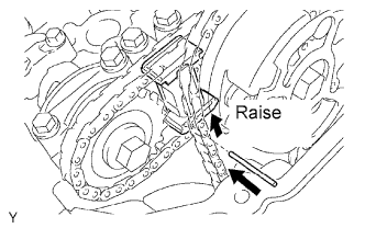
While raising up the No. 2 chain tensioner, insert a diameter of 1.0 mm (0.039 in.) into the hole to fix it.
-
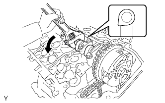
Hold the hexagonal portion of the No. 2 camshaft with a wrench, and remove the camshaft timing gear set bolt.
Note
Be careful not to damage the cylinder head and valve lifter with the wrench.
-
Separate the camshaft timing gear from the No. 2 camshaft.
-
Rotate the camshaft counterclockwise using the wrench so that the cam lobes of the No. 1 cylinder faces upward as shown in the illustration.
-
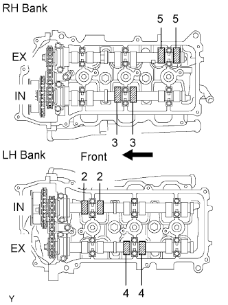
Uniformly loosen and remove the 8 bearing cap bolts in several passes in the sequence shown in the illustration.
-
Remove the 4 bearing caps and No. 2 camshaft.
-
-
Remove the No. 2 chain tensioner.
-
Remove the No. 2 chain tensioner bolt, and then remove the No. 2 chain tensioner and camshaft timing gear.
-
-
Remove the No. 1 camshaft.
Note
As the thrust clearance of the camshaft is small, the camshaft must be kept level while it is being removed. If the camshaft is not kept level, the portion of the cylinder head which are received the shaft thrust may crack or be damaged, causing the camshaft to seize or break. To avoid this, the following steps should be carried out.
-
Hold the hexagonal portion of the No. 1 camshaft with a wrench, and loosen the camshaft timing gear set bolt.
Note
-
Be careful not to damage the cylinder head and valve lifter with the wrench.
-
Do not disassemble the camshaft timing gear assembly.
-
-
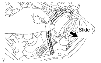
Slide the camshaft timing gear and separate the No. 1 chain from the camshaft timing gear.
-
Rotate the No. 1 camshaft counterclockwise using the wrench so that the cam lobes of No. 1 cylinder faces upward as shown in the illustration.
-
Uniformly loosen and remove the 8 bearing cap bolts in several passes in the sequence shown in the illustration.
-
Remove the 4 bearing caps.
-
Remove the camshaft timing gear set bolt with the No. 1 camshaft lifted up, and then remove the No. 1 camshaft and camshaft timing gear w/ No. 2 chain.
-
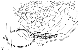
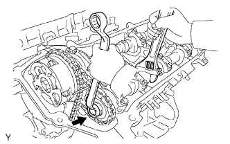
Tie the No. 1 chain with a string as shown in the illustration.
Note
Be careful not to drop anything inside the timing chain cover.
-
-
Remove the No. 4 camshaft.
Note
As the thrust clearance of the camshaft is small, the camshaft must be kept level while it is being removed. If the camshaft is not kept level, the portion of the cylinder head which are received the shaft thrust may crack or be damaged, causing the camshaft to seize or break. To avoid this, the following steps should be carried out.
-
While pushing down the No. 3 chain tensioner, insert a pin of diameter of 1.0 mm (0.039 in.) into the hole to fix it.
-
Hold the hexagonal portion of the No. 4 camshaft with a wrench, and remove the camshaft timing gear set bolt.
Note
Be careful not to damage the cylinder head and valve lifter with the wrench.
-
Separate the camshaft timing gear from the No. 4 camshaft.
-
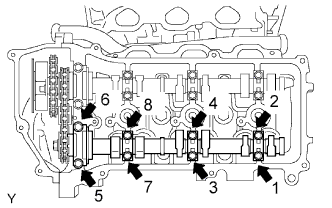
Uniformly loosen and remove the 8 bearing cap bolts in several passes in the sequence shown in the illustration.
-
Remove the 4 bearing caps and No. 4 camshaft.
-
-
Remove the No. 3 chain tensioner assembly.
-
Remove the No. 3 chain tensioner bolt, and then remove the No. 3 chain tensioner and camshaft timing gear.
-
-
Remove the No. 3 camshaft sub-assembly
Note
As the thrust clearance of the camshaft is small, the camshaft must be kept level while it is being removed. If the camshaft is not kept level, the portion of the cylinder head which received the shaft thrust may crack or be damaged, causing the camshaft to seize or break. To avoid this, the following steps should be carried out.
-
Using several steps, loosen and remove the 8 bearing cap bolts uniformly in the sequence as shown in the illustration.
-
Remove the 4 bearing caps.
-
Hold the No. 1 chain, and remove the No. 3 camshaft, camshaft timing gear and No. 2 chain.
-
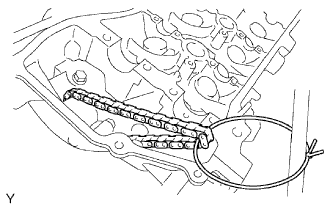
Tie the No. 1 chain with a string as shown in the illustration.
Note
Be careful not to drop anything inside the timing chain cover.
-
-
Remove the valve lifters.
-
Determine the replacement valve lifter size according to these Formula or Charts:
-
Using a micrometer, measure the thickness of the removed lifter.
-
Calculate the thickness of a new lifter so that the valve clearance comes within the specified value.
T Thickness of removed lifter A Measured valve clearance N Thickness of new lifter Intake N = T + (A to 0.20 mm (0.008 in.)) Exhaust N = T + (A to 0.30 mm (0.012 in.)) -
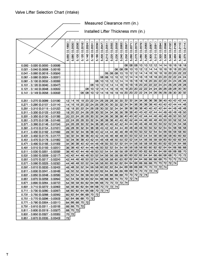
Select a new intake side lifter with a thickness as close as possible to the calculated value.
Tech Tips
Lifters are available in 35 sizes in increments of 0.020 mm (0.0008 in.), from 5.060 mm (0.1992 in.) to 5.740 mm (0.2260 in.).
-
Valve lifter selection chart (intake).
-
Valve lifter selection chart (intake) (continued).
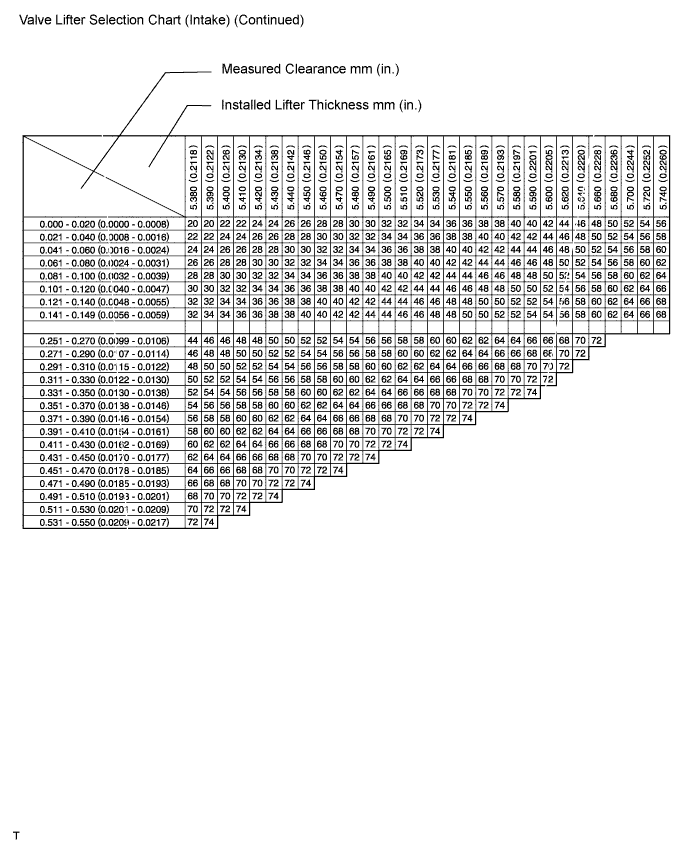
New lifter thickness mm (in.) No. Thickness No. Thickness No. Thickness 06 5.060 (0.1992) 30 5.300 (0.2087) 54 5.540 (0.2181) 08 5.080 (0.2000) 32 5.320 (0.2094) 56 5.560 (0.2189) 10 5.100 (0.2008) 34 5.340 (0.2102) 58 5.580 (0.2197) 12 5.120 (0.2016) 36 5.360 (0.2110) 60 5.600 (0.2205) 14 5.140 (0.2024) 38 5.380 (0.2118) 62 5.620 (0.2213) 16 5.160 (0.2031) 40 5.400 (0.2126) 64 5.640 (0.2220) 18 5.180 (0.2039) 42 5.420 (0.2134) 66 5.660 (0.2189) 20 5.200 (0.2047) 44 5.440 (0.2142) 68 5.680 (0.2236) 22 5.220 (0.2055) 46 5.460 (0.2150) 70 5.700 (0.2244) 24 5.240 (0.2063) 48 5.480 (0.2157) 72 5.720 (0.2252) 26 5.260 (0.2071) 50 5.500 (0.2165) 74 5.740 (0.2260) 28 5.280 (0.2079) 52 5.520 (0.2173) Intake valve clearance (Cold) 0.15 to 0.25 mm (0.006 to 0.010 in.) Example:
The 5.250 mm (0.2067 in.) lifter is installed, and the measured clearance is 0.400 mm (0.0158 in.)
Replace the 5.250 mm (0.2067 in.) lifter with a new No. 46 lifter.
-
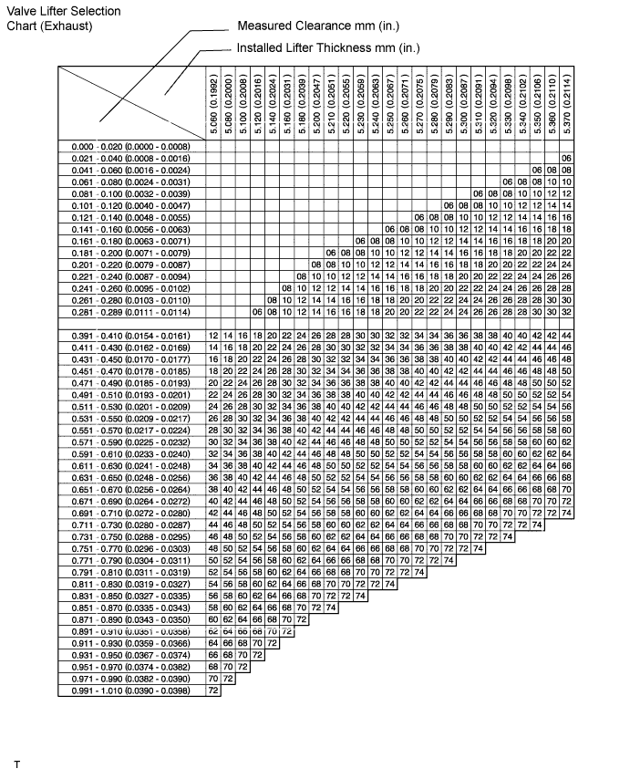
Valve lifter selection chart (exhaust).
-
Valve lifter selection chart (exhaust) (continued).
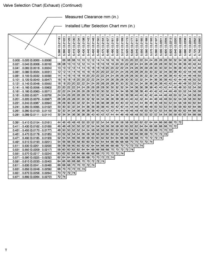
New lifter thickness mm (in.) No. Thickness No. Thickness No. Thickness 06 5.060 (0.1992) 30 5.300 (0.2087) 54 5.540 (0.2181) 08 5.080 (0.2000) 32 5.320 (0.2094) 56 5.560 (0.2189) 10 5.100 (0.2008) 34 5.340 (0.2102) 58 5.580 (0.2197) 12 5.120 (0.2016) 36 5.360 (0.2110) 60 5.600 (0.2205) 14 5.140 (0.2024) 38 5.380 (0.2118) 62 5.620 (0.2213) 16 5.160 (0.2031) 40 5.400 (0.2126) 64 5.640 (0.2220) 18 5.180 (0.2039) 42 5.420 (0.2134) 66 5.660 (0.2189) 20 5.200 (0.2047) 44 5.440 (0.2142) 68 5.680 (0.2236) 22 5.220 (0.2055) 46 5.460 (0.2150) 70 5.700 (0.2244) 24 5.240 (0.2063) 48 5.480 (0.2157) 72 5.720 (0.2252) 26 5.260 (0.2071) 50 5.500 (0.2165) 74 5.740 (0.2260) 28 5.280 (0.2079) 52 5.520 (0.2173) Exhaust valve clearance (Cold) 0.29 to 0.39 mm (0.011 to 0.015 in.) Example:
The 5.340 mm (0.2102 in.) lifter is installed, and the measured clearance is 0.480 mm (0.0189 in.)
Replace the 5.340 mm (0.2102 in.) lifter with a new No. 48 lifter.
Tech Tips
Lifters are available in 35 sizes in increments of 0.020 mm (0.0008 in.), from 5.060 mm (0.1992 in.) to 5.740 mm (0.2260 in.).
-
-
Install the No. 3 camshaft.
Note
As the thrust clearance of the camshaft is small, the camshaft must be kept level while it is being installed. If the camshaft is not kept level, the portion of the cylinder head which receives the shaft thrust may crack or be damaged, causing the camshaft to seize or break. To avoid this, the following steps should be carried out.
-
Align the mark link (yellow) with the timing mark (2 dot marks) of the camshaft timing gear as shown in the illustration.
-
Apply new engine oil to the thrust portion and journal of the camshafts.
-
Temporarily put the No. 1 chain on the No. 2 chain of the camshaft timing gear.
-
Set the No. 3 camshaft onto the LH cylinder head with the cam lobes of the No. 2 cylinder faces downward as shown in the illustration.
-
Install the 4 bearing caps in their proper locations.
-
Apply a light coat of engine oil on the threads of the bearing cap bolts.
-
Install the 8 bearing cap bolts. Using several steps, tighten the bolts uniformly in the sequence as shown in the illustration.
- Torque:
- 9.0 N*m { 92 kgf*cm, 80 in.*lbf, for 10 mm (0.39 in.) head }
- 24 N*m { 245 kgf*cm, 18 in.*lbf, for 12 mm (0.47 in.) head (A) }
-
Set the paint mark of the No. 1 chain between the timing marks of the camshaft timing gear.
-
-
Install the No. 3 chain tensioner.
-
While pushing in the tensioner, insert a diameter 1.0 mm (0.039 in.) pin into the hole to hold to fix it in place.
-
Temporarily install the camshaft timing gear and No. 3 chain tensioner and align the mark links (yellow) with the timing marks (1 dot mark and 2 dot marks) of the camshaft timing gears.
-
Tighten the No. 3 chain tensioner bolt.
- Torque:
- 19 N*m { 194 kgf*cm, 14 ft.*lbf }
-
-
Install the No. 4 camshaft sub-assembly.
Note
As the thrust clearance of the camshaft is small, the camshaft must be kept level while it is being installed. If the camshaft is not kept level, the portion of the cylinder head which receives the shaft thrust may crack or be damaged, causing the camshaft to seize or break. To avoid this, the following steps should be carried out.
-
Align the knock pin hole in the camshaft timing gear with the knock pin of the No. 4 camshaft, and insert the No. 4 camshaft into the camshaft timing gear.
-
Temporarily install the camshaft timing gear set bolt.
-
Install the 4 bearing caps in their proper locations.
-
Apply a light coat of engine oil on the threads and under the heads of the bearing cap bolts.
-
Install the 8 bearing cap bolts. Using several steps, tighten the bolts uniformly in the sequence as shown in the illustration.
- Torque:
- 9.0 N*m { 92 kgf*cm, 80 in.*lbf, for 10 mm (0.39 in.) head }
- 24 N*m { 245 kgf*cm, 18 ft.*lbf, for 12 mm (0.47 in.) head (A) }
-
Hold the hexagonal portion of the No. 4 camshaft with a wrench, and tighten the camshaft timing gear set bolt.
- Torque:
- 100 N*m { 1,020 kgf*cm, 74 ft.*lbf }
-
Remove the pin from the No. 3 chain tensioner.
-
-
Install the camshaft.
Note
As the thrust clearance of the camshaft is small, the camshaft must be kept level while it is being installed. If the camshaft is not kept level, the portion of the cylinder head which receives the shaft thrust may crack or be damaged, causing the camshaft to seize or break. To avoid this, the following steps should be carried out.
-
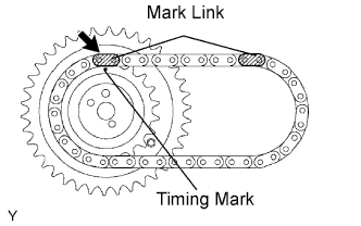
Align the mark link (yellow) with the timing mark (1 dot mark) of the camshaft timing gear as shown in the illustration.
-
Apply new engine oil to the thrust portion and journal of the camshafts.
-
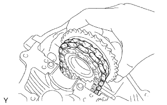
Temporarily put the No. 1 chain on the No. 2 chain of the camshaft timing gear.
-
Align the knock pin hole in the camshaft timing gear with the knock pin of the No. 1 camshaft, and insert the No. 1 camshaft into the camshaft timing gear.
-
Temporarily install the camshaft timing gear set bolt.
-
Set the No. 1 camshaft onto the RH cylinder head with the cam lobes of the No. 1 cylinder faces downward as shown in the illustration.
-
Install the 4 bearing caps in their proper locations.
-
Apply a light coat of engine oil on the threads and under the heads of the bearing cap bolts.
-
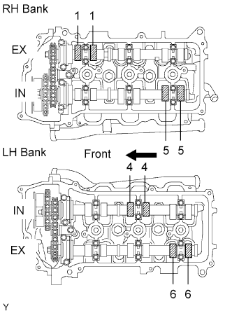
Install the 8 bearing cap bolts. Using several steps, tighten the bolts uniformly in the sequence as shown in the illustration.
- Torque:
- 9.0 N*m { 92 kgf*cm, 80 in.*lbf, for 10 mm (0.39 in.) head }
- 24 N*m { 245 kgf*cm, 18 ft.*lbf, for 12 mm (0.39 in.) head (A) }
-
Rotate the No. 1 camshaft clockwise using hexagonal portion of the No. 1 camshaft so that the timing mark of the camshaft timing gear is aligned with the timing marks of the camshaft bearing cap.
-
Align the paint mark of the No. 1 chain with the timing mark of the camshaft timing gear.
-
Hold the hexagonal portion of the No. 1 camshaft with a wrench, and tighten the camshaft timing gear set bolt.
- Torque:
- 100 N*m { 1,020 kgf*cm, 74 ft.*lbf }
-
-
Install the No. 2 chain tensioner.
-
While pushing in the tensioner, insert a diameter of 1.0 mm (0.039 in.) pin into the hole to fix it in place.
-
Temporarily install the camshaft timing gear and No. 2 chain tensioner and align the mark links (yellow) with the timing marks (1 dot mark) of the camshaft timing gears.
-
Tighten the chain tensioner No. 2 bolt.
- Torque:
- 19 N*m { 194 kgf*cm, 14 ft.*lbf }
-
-
Install the No. 2 camshaft.
Note
As the thrust clearance of the camshaft is small, the camshaft must be kept level while it is being installed. If the camshaft is not kept level, the portion of the cylinder head which receives the shaft thrust may crack or be damaged, causing the camshaft to seize or break. To avoid this, the following steps should be carried out.
-
Set the No. 2 camshaft onto the RH cylinder head with the cam lobes of No. 1 cylinder faces upward as shown in the illustration.
-
Install the 4 bearing caps in their proper locations.
-
Apply a light coat of engine oil on the threads and under the heads of the bearing cap bolts.
-
Install the 8 bearing cap bolts. Using several steps, tighten the bolts uniformly in the sequence as shown in the illustration.
- Torque:
- 9.0 N*m { 92 kgf*cm, 80 in.*lbf, for 10 mm (0.39 in.) head }
- 24 N*m { 245 kgf*cm, 18 ft.*lbf, for 12 mm (0.47 in.) head (A) }
-
Rotate the No. 2 camshaft clockwise using the wrench so that the knock pin of the No. 2 camshaft is aligned with the knock pin hole of the camshaft timing gear.
-
Hold the hexagonal portion of the No. 2 camshaft with a wrench, and install the camshaft timing gear set bolt.
- Torque:
- 100 N*m { 1,020 kgf*cm, 74 ft.*lbf }
-
Remove the pin from the No. 2 chain tensioner.
-
-
Install the No. 1 chain tensioner.
-
While turning the stopper plate of the tensioner clockwise, push in the plunger of the tensioner as shown in the illustration.
-
While turning the stopper plate of the tensioner counterclockwise, insert a bar of diameter of 3.5 mm (0.138 in.) into the holes in the stopper plate and tensioner to fix the stopper plate.
-
Install the chain tensioner with the 2 bolts.
- Torque:
- 10 N*m { 102 kgf*cm, 7 ft.*lbf }
-
Remove the bar from the chain tensioner.
-
Install a new gasket and the timing chain cover plate with the 4 bolts.
- Torque:
- 9.0 N*m { 92 kgf*cm, 80 in.*lbf }
-
Slowly turn the crankshaft pulley 2 complete revolutions, and align the notch with timing mark 0 of the timing chain cover.
-
Check that the timing marks of the camshaft timing gears are aligned with the timing marks of the bearing cap as shown in the illustration.
-
-
-
INSTALL CYLINDER HEAD COVER LH
-
Remove any old packing (FIPG) material and be careful not to drop any oil on the contact surfaces of the cylinder head, timing chain cover and cylinder head cover.
-
Apply adhesive on the threads of the ventilation valve.
Adhesive Toyota Genuine Adhesive 1324, Three Bond 1324 or equivalent -
Install the ventilation valve to the cylinder head cover.
- Torque:
- 27 N*m { 275 kgf*cm, 20 ft.*lbf }
-
Install the gasket to the cylinder head cover.
-
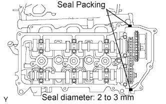
Apply a continuous bead of the seal packing to the cylinder head and timing chain cover as shown in the illustration.
Seal packing Toyota Genuine Seal Packing Black, Three Bond 1207B or equivalent Seal diameter 2 to 3 mm (0.08 to 0.12 in.) Note
Install the cylinder head cover within 3 minutes after applying seal packing. After installing it, cylinder head cover bolts and nuts must be tightened within 15 minutes. Otherwise the seal packing must be removed and reapplied.
-
Install the seal washers to the bolts.
-
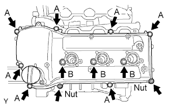
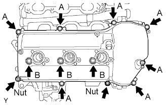
Install the cylinder head cover with the 10 bolts and 2 nuts. Uniformly tighten the bolts and nuts in several passes.
- Torque:
- 10 N*m { 102 kgf*cm, 7 ft.*lbf, for bolt A }
- 9.0 N*m { 92 kgf*cm, 80 in.*lbf, for bolt B }
- 9.0 N*m { 92 kgf*cm, 80 in.*lbf, for nut }
-
-
INSTALL CYLINDER HEAD COVER RH
-
Remove any old packing (FIPG) material and be careful not to drop any oil on the contact surfaces of the cylinder head, timing chain cover and cylinder head cover.
-
Install the gasket to the cylinder head cover.
-
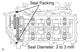
Apply a continuous bead of the seal packing to the cylinder head and timing chain cover as shown in the illustration.
Seal packing Toyota Genuine Seal Packing Black, Three Bond 1207B or equivalent Seal diameter 2 to 3 mm (0.08 to 0.12 in.) Note
Install the cylinder head cover within 3 minutes after applying seal packing. After installing it, cylinder head cover bolts and nuts must be tightened within 15 minutes. Otherwise the seal packing must be removed and reapplied.
-
Install the seal washers to the bolts.
-
Install the cylinder head cover with the 10 bolts and 2 nuts. Uniformly tighten the bolts and nuts in several passes.
- Torque:
- 10 N*m { 102 kgf*cm, 7 ft.*lbf, for bolt A }
- 9.0 N*m { 92 kgf*cm, 80 in.*lbf, for bolt B }
- 9.0 N*m { 92 kgf*cm, 80 in.*lbf, for nut }
-
-
INSTALL IGNITION COIL
- Torque:
- 10 N*m { 102 kgf*cm, 7 ft.*lbf }
-
INSTALL INTAKE AIR SURGE TANK
-
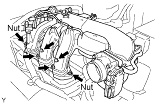
Install a new gasket to the intake air surge tank.
-
Using an 8 mm hexagon socket wrench, install the intake air surge tank with the 4 bolts. Install the 2 nuts.
- Torque:
- 28 N*m { 286 kgf*cm, 21 ft.*lbf }
-
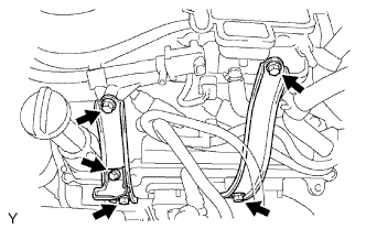
Install the 2 surge tank stays with the 4 bolts.
- Torque:
- 21 N*m { 214 kgf*cm, 15 ft.*lbf }
-
Install the oil baffle plate with the bolt.
- Torque:
- 9.0 N*m { 92 kgf*cm, 80 in.*lbf }
-
Install the throttle body bracket with the 2 bolts.
- Torque:
- 21 N*m { 214 kgf*cm, 15 ft.*lbf }
-
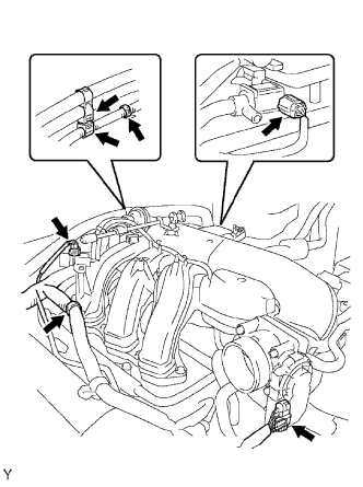
Install the 3 wire harness clamps and hose clamp.
-
Connect the throttle body with motor connector.
-
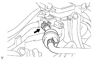
Connect the 2 VSV connectors.
-
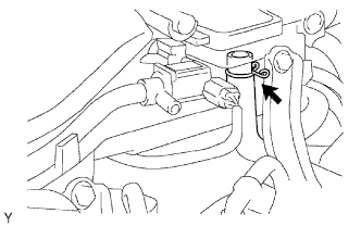
Connect the ventilation hose.
-
Connect the purge line hose.
-
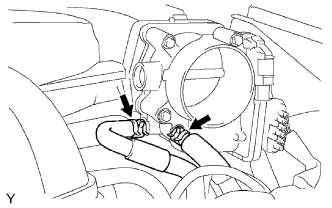
Connect the 2 water by-pass hoses.
-
-
INSTALL AIR CLEANER
- Torque:
- 8.0 N*m { 82 kgf*cm, 71 in.*lbf }
-
CONNECT NO. 2 VENTILATION HOSE
-
CONNECT CABLE TO BATTERY NEGATIVE TERMINAL
-
PERFORM INITIALIZATION
-
Perform initialization Click here.
Note
Certain systems need to be initialized after disconnecting and reconnecting the cable from the negative (-) battery terminal.
-
-
ADD ENGINE COOLANT
-
Tighten all the plugs and fill the radiator with TOYOTA Super Long Life Coolant (SLLC).
- Torque:
- 13 N*m { 130 kgf*cm, 9 ft.*lbf, for cylinder block drain cock plug }
Standard Capacity 9.8 liters (10.4 US qts, 8.6 Imp. qts) Tech Tips
-
TOYOTA vehicles are filled with TOYOTA SLLC at the factory. In order to avoid damage to the engine cooling system and other technical problems, only use TOYOTA SLLC or similar high quality ethylene glycol based non-silicate, non-amine, non-nitrite, non-borate coolant with long-life hybrid organic acid technology (coolant with long-life hybrid organic and technology consists of a combination of low phosphates and organic acids).
-
Please contact your TOYOTA dealer for further details.
Note
Never use water as a substitute for engine coolant.
-
Press the inlet and outlet radiator hoses several times by hand, and then check the level of the coolant.
-
Install the radiator cap.
-
Bleed air from the cooling system.
-
Warm up the engine until the thermostat opens. While the thermostat is open, circulate the coolant for several minutes.
-
Maintain the engine speed at 2,000 to 2,500 rpm.
-
Press the inlet and outlet radiator hoses several times by hand to bleed air.
CAUTION:
When pressing the radiator hoses:
-
Wear protective gloves.
-
Be careful as the radiator hoses are hot.
-
Keep your hands away from the radiator fan.
-
-
-
Stop the engine and wait until the coolant cools down to ambient temperature.
CAUTION:
Do not remove the radiator cap while the engine and radiator are still hot. Pressurized, hot engine coolant and steam may be released and cause serious burns.
-
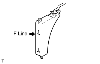
Check the coolant level in the radiator reservoir.
If the coolant level is low, add SLLC to the reservoir F line.
-
-
CHECK FOR ENGINE COOLANT LEAKS
CAUTION:
Do not remove the radiator cap while the engine and radiator are still hot. Pressurized, hot engine coolant and steam may be released and cause serious burns.
-
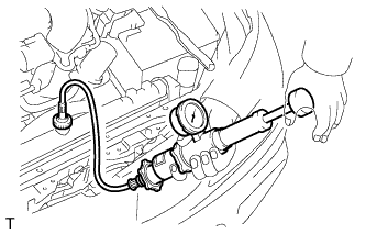
Fill the radiator with coolant and attach a radiator cap tester.
-
Warm up the engine.
-
Using the radiator cap tester, increase the pressure inside the radiator to 118 kPa (1.2 kgf/cm2, 17.1 psi), and check that the pressure does not drop.
If the pressure drops, check the hoses, radiator and water pump for leaks. If no external leaks are found, check the cylinder block and head.
-
-
INSTALL V-BANK COVER
-
Install the V-bank cover with the 2 nuts.
- Torque:
- 7.5 N*m { 76 kgf*cm, 66 in.*lbf }
-
-
INSPECT IGNITION TIMING
-
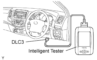
When using intelligent tester:
Check the ignition timing.
-
Connect the intelligent tester to the DLC3.
Tech Tips
Please refer to the intelligent tester operator's manual for further details.
Ignition timing 7 to 24°BTDC @ idle (Transmission in neutral position) -
Disconnect the intelligent tester from the DLC3.
-
-
When not using intelligent tester.
Check the ignition timing.
-
Remove the air cleaner cap.
-
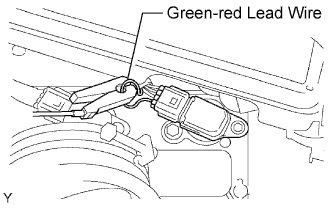
Connect the tester probe of a timing light to the green-red read wire of the ignition coil connector for the No.1 cylinder.
-
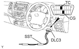
Using SST, connect terminals TC and CG of the DLC3.
- SST
- 09843-18040
-
Using the timing light, check the ignition timing.
Ignition timing 10 +- 2° BTDC @ idle (Transmission in neutral position) -
Remove the SST from the DLC3.
-
Check the ignition timing.
Ignition timing 7 to 24° BTDC @ idle (Transmission in neutral position) -
Disconnect the timing light from the engine.
-
Install the air cleaner cap.
-
-