AIR CONDITIONING UNIT INSTALLATION
PROCEDURE
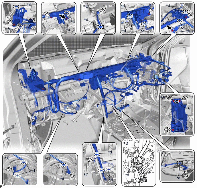
INSTALL AIR CONDITIONING HARNESS ASSEMBLY (for Automatic Air Conditioning System)
Route the air conditioning harness assembly as shown in the illustration.
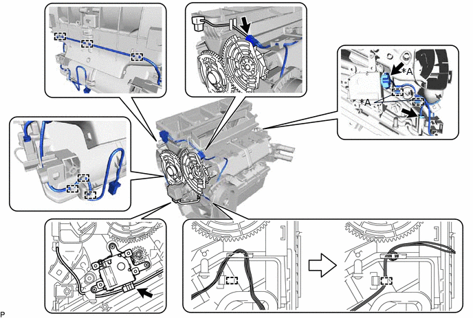
*A
for Dual Type
-
-
Connect each connector.
Engage each clamp to install the air conditioning harness assembly.
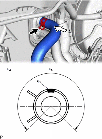
INSTALL DRAIN COOLER HOSE
-
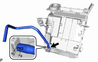
*a
Hose Notch
*b
Rib
Align the hose notch with the rib as shown in the illustration and install the drain cooler hose.
-
INSTALL AIR CONDITIONING AMPLIFIER ASSEMBLY (for Manual Air Conditioning System)
Temporarily install the air conditioning amplifier assembly as shown in the illustration.
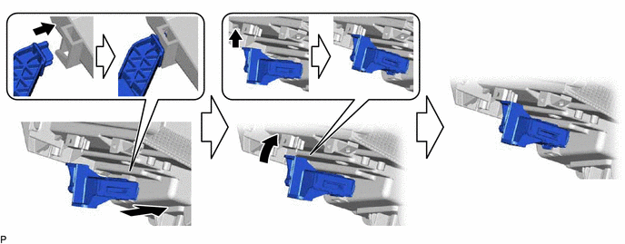
Install the air conditioning amplifier assembly with the screw.
INSTALL AIR CONDITIONING AMPLIFIER ASSEMBLY (for Automatic Air Conditioning System)
Temporarily install the air conditioning amplifier assembly as shown in the illustration.
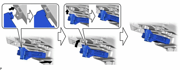
Install the air conditioning amplifier assembly with the screw.
Connect the connector.
INSTALL CONSOLE MOUNTING BRACKET RH
Engage the 2 claws to install the console mounting bracket RH.
INSTALL CONSOLE MOUNTING BRACKET LH
Install the console mounting bracket LH with the screw.
INSTALL ASPIRATOR PIPE (w/o Cooler System)
Engage the 2 claws to install the aspirator pipe.
INSTALL ASPIRATOR (for Automatic Air Conditioning System)
for LHD:
Engage the 2 claws to install the aspirator.
for RHD:
Engage the 2 claws to install the aspirator.
Engage the clamp.
INSTALL HEATER COVER (except Cold Area)
Engage the 4 claws to install the heater cover.
INSTALL AIR CONDITIONING RADIATOR ASSEMBLY
Install the air conditioning radiator assembly with the 3 screws.
for Automatic Air Conditioning System:
Connect the connector.
for Cold Area:
Engage each clamp.
Connect the wire harness with the screw.
INSTALL NO. 3 AIR DUCT SUB-ASSEMBLY
Engage the 2 claws to install the No. 3 air duct sub-assembly.
Note:If any of the claws of the No. 3 air duct sub-assembly are cracked or deformed, make sure to replace the air duct with a new one. Failure to do so may cause the No. 3 air duct sub-assembly to fall off or noise to occur.
INSTALL NO. 2 AIR DUCT SUB-ASSEMBLY
Engage the 2 claws to install the No. 2 air duct sub-assembly.
Note:If any of the claws of the No. 2 air duct sub-assembly are cracked or deformed, make sure to replace the air duct with a new one. Failure to do so may cause the No. 2 air duct sub-assembly to fall off or noise to occur.
TEMPORARILY INSTALL AIR CONDITIONER UNIT ASSEMBLY
Temporarily install the air conditioner unit assembly with the bolt and nut.
Note:To prevent damage to the installation bracket for the air conditioner unit assembly, be sure to support the air conditioner unit assembly.
Connect the drain cooler hose.
INSTALL INSTRUMENT PANEL REINFORCEMENT ASSEMBLY
Install the instrument panel reinforcement assembly with the 5 bolts <A>.
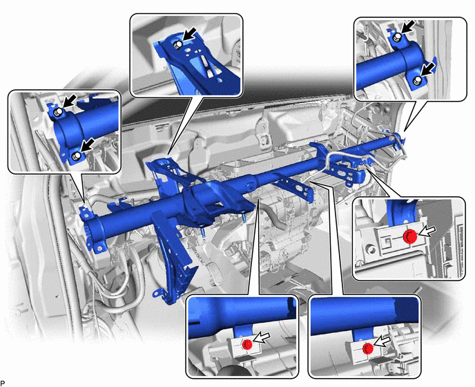

Bolt <A>

Bolt <B>
Temporarily install the 3 bolts <B>.
INSTALL NO. 2 INSTRUMENT PANEL BRACE SUB-ASSEMBLY
Install the No. 2 instrument panel brace sub-assembly with the bolt, screw and nut.
Tip:Do not fully tighten the screw.
-
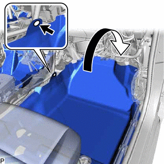
Install the front floor carpet assembly to the original position as shown in the illustration.
Install the clip.
INSTALL NO. 1 INSTRUMENT PANEL BRACE SUB-ASSEMBLY
Install the No. 1 instrument panel brace sub-assembly with the bolt, screw and nut.
Tip:Do not fully tighten the screw.
-
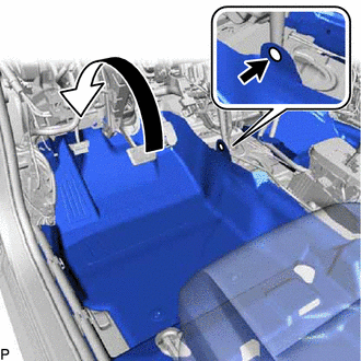
Install the front floor carpet assembly to the original position as shown in the illustration.
Install the clip.
INSTALL INSTRUMENT PANEL WIRE (for LHD)
Engage each clamp.
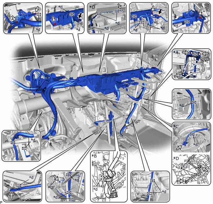
*A
w/ ECU Integration Box RH
*B
w/o Radio Receiver
*C
for Automatic Air Conditioning System
*D
for Manual Air Conditioning System
*a
Ground Portion of the Wiring Harness Protector Cover
*b
Earth Wire
*c
Guide
*d
Clamp
Bolt <A>
Bolt <B>

Bolt <C>

Connector
Connect each connector.
w/ ECU Integration Box RH:
Engage the guide to connect the ECU integration box RH.
Install the 3 bolts <C>.
12 N*m
122 kgf*cm
9 ft.*lbf
Connect the instrument panel wire with the 5 bolts <B>.
Connect the ground portion of the wiring harness protector cover and earth wire with the 2 bolts <A>.
8.5 N*m
87 kgf*cm
75 in.*lbf
for Cold Area:
Connect the 2 connectors.
INSTALL INSTRUMENT PANEL WIRE (for RHD)
Engage each clamp.
*A
w/ ECU Integration Box RH
*B
w/o Radio Receiver
*C
for Manual Air Conditioning System
*D
for Automatic Air Conditioning System
*a
Ground Portion of the Wiring Harness Protector Cover
*b
Earth Wire
*c
Guide
*d
Clamp
Bolt <A>
Bolt <B>
Bolt <C>
Connector
Connect each connector.
w/ ECU Integration Box RH:
Engage the guide to connect the ECU integration box RH.
Install the 3 bolts <C>.
12 N*m
122 kgf*cm
9 ft.*lbf
Connect the instrument panel wire with the 4 bolts <B>.
Connect the ground portion of the wiring harness protector cover and earth wire with the 2 bolts <A>.
8.5 N*m
87 kgf*cm
75 in.*lbf
for Cold Area:
Connect the 2 connectors.
FULLY TIGHTEN AIR CONDITIONER UNIT ASSEMBLY (for LHD)
Tighten the 4 bolts, 2 screws and nut.
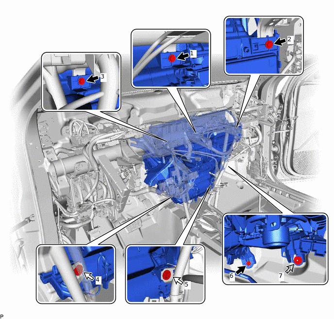
Bolt
Screw
Nut
-
-
Bolt, Nut
9.8 N*m
100 kgf*cm
87 in.*lbf
Screw
4.0 N*m
41 kgf*cm
35 in.*lbf
Note:Tighten the bolts, screws and nut in the order shown in the illustration to install the air conditioner unit assembly.
FULLY TIGHTEN AIR CONDITIONER UNIT ASSEMBLY (for RHD)
Tighten the 4 bolts, 2 screws and nut.
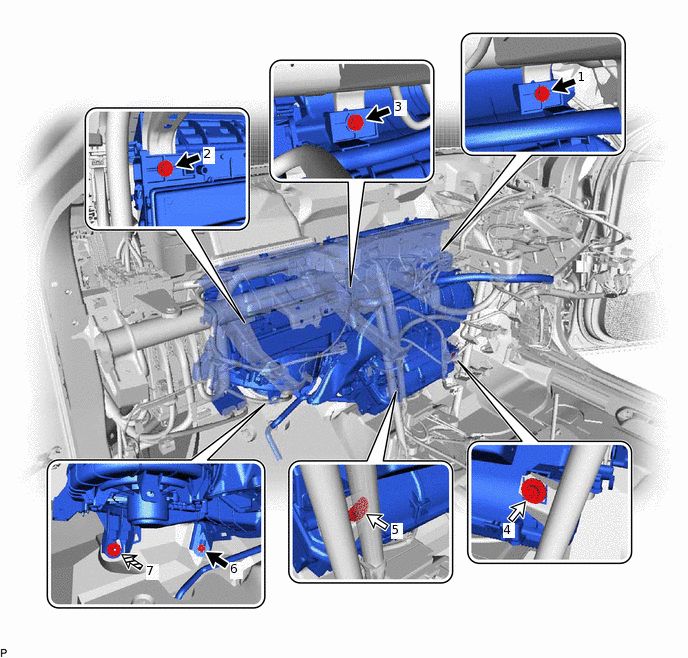
Bolt
Screw
Nut
-
-
Bolt, Nut
9.8 N*m
100 kgf*cm
87 in.*lbf
Screw
4.0 N*m
41 kgf*cm
35 in.*lbf
Note:Tighten the bolts, screws and nut in the order shown in the illustration to install the air conditioner unit assembly.
INSTALL CENTER INSTRUMENT PANEL TO COWL BRACE
Install the center instrument panel to cowl brace with the 2 bolts.
INSTALL DEFROSTER NOZZLE ASSEMBLY
Engage the 6 claws to install the defroster nozzle assembly.
INSTALL COOLER (ROOM TEMP. SENSOR) THERMISTOR (for Automatic Air Conditioning System)
Connect the connector and aspirator to install the cooler (room temp. sensor) thermistor.
INSTALL REAR NO. 1 AIR DUCT (for Cold Area)
Engage the 8 claws to install the rear No. 1 air duct.
INSTALL TELEMATICS TRANSCEIVER (w/ Manual (SOS) Switch)
INSTALL DRIVING SUPPORT ECU ASSEMBLY (for 1ND-TV)
w/ Cruise Control System:
INSTALL INSTRUMENT PANEL JUNCTION BLOCK ASSEMBLY WITH MAIN BODY ECU (for LHD)
INSTALL INSTRUMENT PANEL JUNCTION BLOCK ASSEMBLY WITH MAIN BODY ECU (for RHD)
INSTALL STEERING COLUMN ASSEMBLY
INSTALL LOWER INSTRUMENT PANEL SUB-ASSEMBLY
for Sedan:Click here
for Hatchback, Wagon:Click here
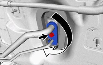
CONNECT HEATER WATER INLET HOSE A
-
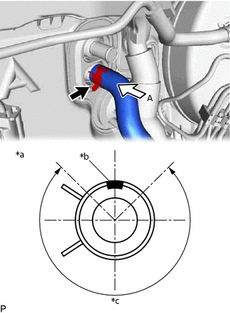
*a
View A
*b
Marking (White)
*c
Clip Installation Angle (270°)
Connect the heater water inlet hose A with the marking (white) facing up and engage the clip within the area shown in the illustration.
Note:Do not apply excessive force to the heater water inlet hose A.
-
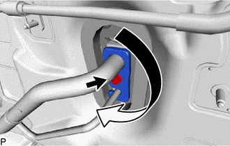
CONNECT HEATER WATER OUTLET HOSE A
-
*a
View A
*b
Marking (white)
*c
Clip Installation Angle (270°)
Connect the heater water outlet hose A with the marking (white) facing up and engage the clip within the area shown in the illustration.
Note:Do not apply excessive force to the heater water outlet hose A.
-
INSTALL COOLER CAP (w/o Cooler System)
Sufficiently apply compressor oil to the 2 O-rings.
Compressor Oil
ND-OIL 8 or equivalent
Install the cooler cap with the bolt.
9.8 N*m
100 kgf*cm
87 in.*lbf
CONNECT AIR CONDITIONER TUBE ASSEMBLY (w/ Cooler System)
w/o Sub-cool Accelerator:
Remove the vinyl tape from the air conditioner tube assembly.
Sufficiently apply compressor oil to a new O-ring and the fitting surface of the air conditioner tube assembly.
Refrigerant
Compressor Oil
HFC-134a (R134a)
ND-OIL 8 or equivalent
HFO-1234yf (R1234yf)
ND-OIL 12 or equivalent
Install the O-ring to the air conditioner tube assembly.
Install the air conditioner tube assembly.
CONNECT SUCTION PIPE SUB-ASSEMBLY (w/ Cooler System)
w/o Sub-cool Accelerator:
Remove the vinyl tape from the suction pipe sub-assembly.
Sufficiently apply compressor oil to a new O-ring and the fitting surface of the suction pipe sub-assembly.
Refrigerant
Compressor Oil
HFC-134a (R134a)
ND-OIL 8 or equivalent
HFO-1234yf (R1234yf)
ND-OIL 12 or equivalent
Install the O-ring to the suction pipe sub-assembly.
Connect the suction pipe sub-assembly.
-
Rotate the hook connector as shown in the illustration.
Insert the pipe joint into the fitting hole securely and install the bolt.
9.8 N*m
100 kgf*cm
87 in.*lbf
CONNECT AIR CONDITIONER TUBE AND ACCESSORY ASSEMBLY (w/ Cooler System)
w/ Sub-cool Accelerator:
Remove the vinyl tape from the air conditioner tube and accessory assembly.
Sufficiently apply compressor oil to 2 new O-rings and the fitting surfaces of the air conditioner tube and accessory assembly.
Compressor Oil
ND-OIL 12 or equivalent
Install the 2 O-rings to the air conditioner tube and accessory assembly.
Connect the air conditioner tube and accessory assembly.
-
Rotate the hook connector as shown in the illustration.
Insert the pipe joint into the fitting hole securely and install the bolt.
9.8 N*m
100 kgf*cm
87 in.*lbf
INSTALL OUTER COWL TOP PANEL (for 1ND-TV)
for LHD:
for Sedan:Click here
for Hatchback, Wagon:Click here
for RHD:
for Sedan:Click here
for Hatchback, Wagon:Click here
INSTALL NO. 2 HEATER AIR DUCT SPLASH SHIELD SEAL (for 1ND-TV)
for LHD:
for Sedan:Click here
for Hatchback, Wagon:Click here
for RHD:
for Sedan:Click here
for Hatchback, Wagon:Click here
INSTALL WATER GUARD PLATE LH (for 1ND-TV)
for LHD:
for Sedan:Click here
for Hatchback, Wagon:Click here
for RHD:
for Sedan:Click here
for Hatchback, Wagon:Click here
INSTALL WINDSHIELD WIPER MOTOR AND LINK ASSEMBLY (for 1ND-TV)
INSPECT FOR COOLANT LEAK (for 1ND-TV)
INSPECT FOR COOLANT LEAK (for 1NR-FE)
INSPECT FOR COOLANT LEAK (for 1ZR-FAE)
INSPECT FOR COOLANT LEAK (for 1ZR-FE)
INSPECT FOR COOLANT LEAK (for 2ZR-FE)
INSPECT FOR COOLANT LEAK (for 8NR-FTS)
INSPECT RESERVOIR TANK ENGINE COOLANT LEVEL (for 1ND-TV)
INSPECT RESERVOIR TANK ENGINE COOLANT LEVEL (for 1NR-FE)
INSPECT RESERVOIR TANK ENGINE COOLANT LEVEL (for 1ZR-FAE)
INSPECT RESERVOIR TANK ENGINE COOLANT LEVEL (for 1ZR-FE)
INSPECT RESERVOIR TANK ENGINE COOLANT LEVEL (for 2ZR-FE)
INSPECT ENGINE COOLANT LEVEL IN RESERVOIR (for 8NR-FTS)
CHARGE AIR CONDITIONING SYSTEM WITH REFRIGERANT (w/ Cooler System)
WARM UP ENGINE (w/ Cooler System)
INSPECT FOR REFRIGERANT LEAK (w/ Cooler System)
INITIALIZE SERVO MOTOR (for Automatic Air Conditioning System)