WORK NOTICES AND PRECAUTIONS PRECAUTIONS FOR POP UP HOOD SYSTEM
-
POP UP HOOD SYSTEM STRUCTURE
Note
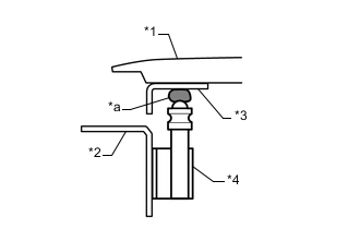
If you are carrying out body repairs that may change the positional relationship between the pop up hood lifter and hood hinge, check for the positional relationship after the body repairs are done (after the hood is fitted and adjusted). (See the figure below.)
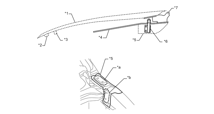
*1 HOOD *2 HOOD LOCK *3 HOOD CUSHION *4 FRONT FENDER APRON *5 COWL TOP SIDE PANEL UPPER *6 POP UP HOOD LIFTER ASSEMBLY *7 HOOD HINGE - - *a Hood Hinge Installation Surface *b Pop Up Hood Lifter Assembly Installation Surface -
TURGET WORK
-
Replacement/correction work of cowl top side panel upper.
-
Replacement/correction work of front fender apron.
-
Body replacement/correction work, including the above-mentioned component parts.
-
-
DERAILS TO BE CHECKED
*1 HOOD *2 FRONT FENDER *3 FRONT FENDER APRON *4 HOOD HINGE *5 POP UP HOOD LIFTER ASSEMBLY *a Relative Angle *b Top/Bottom (vertical) Gap *c Points Of Contact (Front/Back/Left/Right)
-
Relative angle between pop up hood lifter assembly and hood hinge.
-
Gap between pop up hold lifter assembly and hood hinge (top/bottom (vertical) gap).
-
Points of contact during operation of the pop up hood lifter assembly.
-
-
WORK FLOW
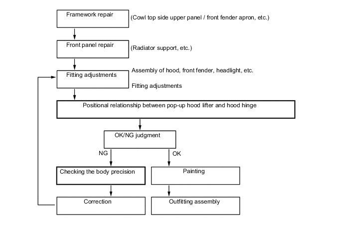
Tech Tips
Checking work must be conducted after the hood is fitted and adjusted.
-
METHODS FOR CHECKING THE POSITIONAL RELATIONSHIP BETWEEN THE POP UP HOOD LIFTER ASSEMBLY AND HOOD HINGE
-
*1 HOOD *2 FRONT FENDER APRON *3 HOOD HINGE *4 POP UP HOOD LIFTER ASSEMBLY *a Clay Checking the top/bottom (vertical) gap.
-
With the hood locked, check the gap between the top edge of the pop up hood lifter assembly and the bottom surface of the hood hinge.
-
Use a gauge or other instrument to make a direct measurement.
Tech Tips
Attach a piece of clay to the top of the pop up hood lifter assembly, close the hood (pressing down the clay), and then measure the thickness of the clay.
-
-
Checking points of contact
-
Check that the points of contact are within the range of the target (stamped mark) on the bottom surface of the hood hinge.
Note
The center of the pop up hood lifter assembly should contact within the target.
-
To check this, first attach a piece of clay to the top of the pop up hood lifter assembly, and then close the hood to press down the piece of clay.
Tech Tips
To check by lowering the hood hinge, first remove the hood.
-
-
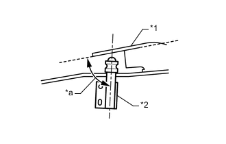
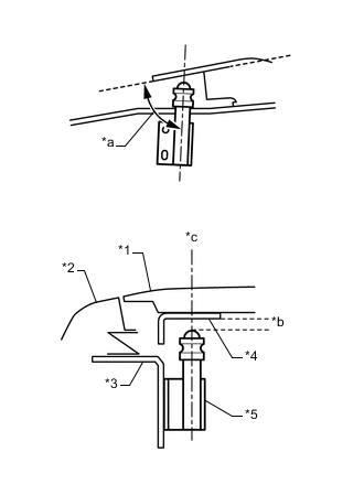
*1 HOOD HINGE *2 POP UP HOOD LIFTER ASSEMBLY *a Relative Angle Checking the relative angle
-
Check the angle after the fitting of the hood is adjusted.
-
Remove the front fender, and check from outside the vehicle.
Tech Tips
If the engine has been removed, check from inside the engine room.
Required precision +/- 2.5° -
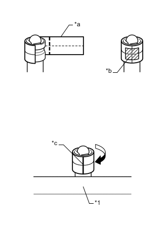
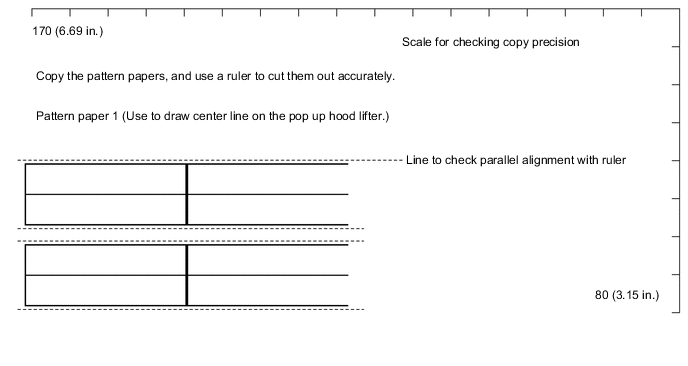
*1 FRONT FENDER APRON *a Pattern Paper 1 *b Tape *c Center Line Use pattern paper 1 to draw a center line on the pop up hood lifter assembly.
-
Attach with the pop-up hood lifter assembly removed or from the engine room side.
-
Align the wrapped area with the height of the line, and fix it in place with the tape.
-
Turn the pattern paper so that the center line faces the vehicle side.
-
-
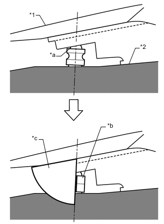
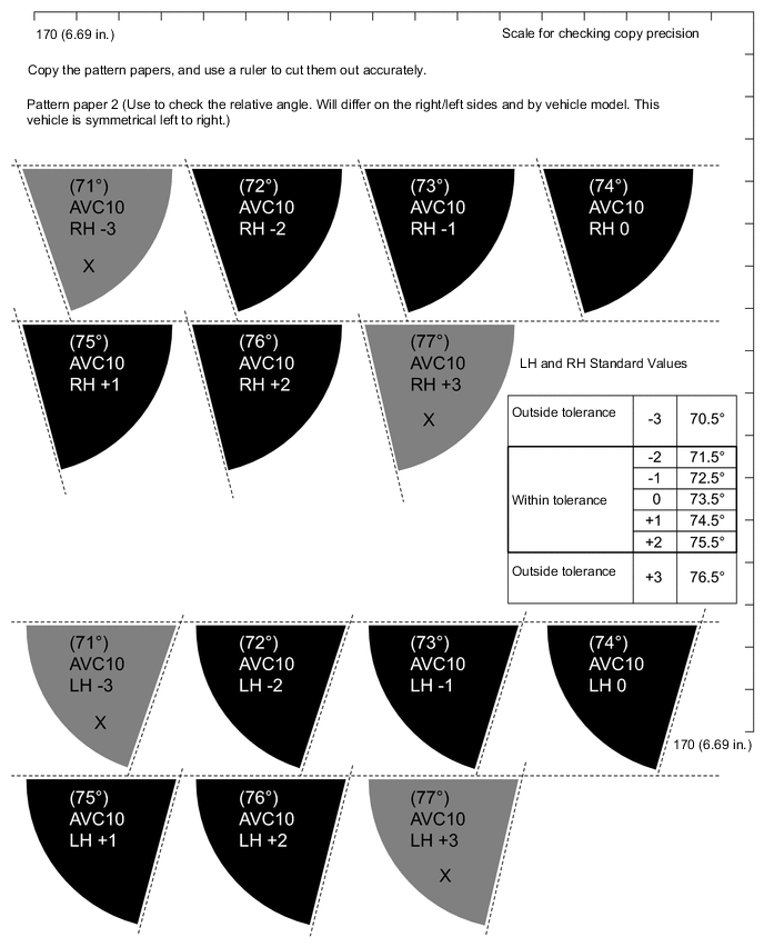
*1 HOOD *2 FRONT FENDER APRON *a Pop Up Hood Lifter Asembly Upper End *b Pattern Paper 1 *c Pattern Paper 2 Align pattern paper 2 to check the relative angle.
Tech Tips
-
The reference angle is different on left/right sides and by vehicle model.
-
Chose the closest of the 7 different types.
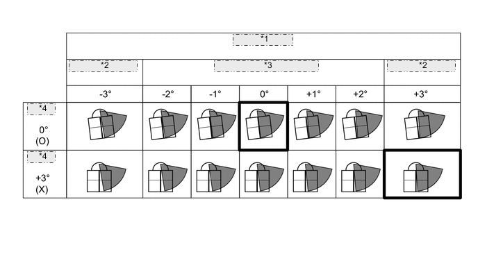
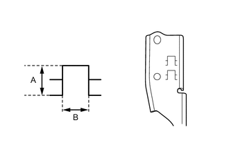
*1 Pattern paper 2 *2 Outside tolerance *3 Within tolerance (+/-2.5°) *4 Example -
-
-
-
PATTERN PAPERS AND TOLERANCE VALUES
Tech Tips
Copy the pattern papers, and use a ruler to cut them out accurately.