EGR VALVE (w/o EGR Cooler) INSPECTION
-
INSPECT ELECTRIC EGR CONTROL VALVE ASSEMBLY (w/ Intercooler)
-
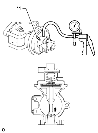
Text in Illustration *1 Cap Inspect the electric EGR control valve.
Tech Tips
Install a cap to block the other port.
-
When a vacuum of 27 kPa (200 mmHg, 7.88 in.Hg) is applied to the diaphragm chamber, check that the shaft rises and that air flows out.
-
While maintaining the above conditions, check that there are no leaks and that the shaft stays in position.
-
Check that the valve does not have heavy carbon deposits and is not stuck.
If the result is not as specified, replace the electric EGR control valve.
-
-
Inspect the EGR valve position sensor.
-

Text in Illustration *a Component without harness connected
(Electric EGR Control Valve)
Measure the resistance according to the value(s) in the table below.
Standard Resistance Tester Connection Condition Specified Condition 1 (VC) - 2 (E2) 20°C (68°F) 2.8 to 7.8 kΩ If the result is not as specified, replace the electric EGR control valve assembly.
-
-
Create a vacuum in the diaphragm chamber.
Tech Tips
Install a cap to block the other port.
-
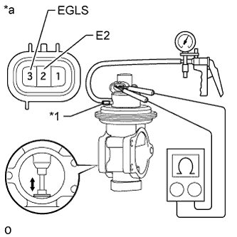
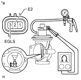
Text in Illustration *1 Cap *a Component without harness connected
(Electric EGR Control Valve)
Measure the resistance according to the value(s) in the table below.
Standard Resistance Tester Connection Condition Specified Condition 3 (EGLS) - 2 (E2) 20°C (68°F)
EGR valve is fully opened
2.0 to 7.0 kΩ 20°C (68°F)
EGR valve is fully closed
0.1 to 2.5 kΩ Tech Tips
The resistance increases in proportion to the opening amount of the EGR valve.
If the result is not as specified, replace the electric EGR control valve assembly.
-
-
INSPECT ELECTRIC EGR CONTROL VALVE ASSEMBLY (w/o Intercooler)
-
Inspect the electric EGR control valve.
-
When a vacuum of 27 kPa (200 mmHg, 7.88 in.Hg) is applied to the diaphragm chamber, check that the shaft rises and air flows out.
-
While maintaining the above conditions, check that there are no leaks and that the shaft stays in position.
-
Check that the valve does not have heavy carbon deposits and is not stuck.
If the result is not as specified, replace the electric EGR control valve assembly.
-
-
Inspect the EGR valve position sensor.
-
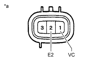
Text in Illustration *a Component without harness connected
(Electric EGR Control Valve)
Measure the resistance according to the value(s) in the table below.
Standard Resistance Tester Connection Condition Specified Condition 1 (VC) - 2 (E2) 20°C (68°F) 2.8 to 7.8 kΩ If the result is not as specified, replace the electric EGR control valve assembly.
-
-
Create a vacuum in the diaphragm chamber.
-
Text in Illustration *a Component without harness connected
(Electric EGR Control Valve)
Measure the resistance according to the value(s) in the table below.
Standard Resistance Tester Connection Condition Specified Condition 3 (EGLS) - 2 (E2) 20°C (68°F)
EGR valve is fully opened
2.0 to 7.0 kΩ 20°C (68°F)
EGR valve is fully closed
0.1 to 2.5 kΩ Tech Tips
The resistance increases in proportion to the opening amount of the EGR valve.
If the result is not as specified, replace the electric EGR control valve assembly.
-