ECD SYSTEM(w/o EGR Cooler), Diagnostic DTC:P0337, P0338
| DTC Code | DTC Name |
|---|---|
| P0337 | Crankshaft Position Sensor "A" Circuit Low Input |
| P0338 | Crankshaft Position Sensor "A" Circuit High Input |
DESCRIPTION
Refer to DTC P0335.
| DTC No. | Detection Item | DTC Detection Condition | Trouble Area | MIL | Memory |
|---|---|---|---|---|---|
| P0337 | Crankshaft Position Sensor "A" Circuit Low Input | Output voltage of crankshaft position sensor is less than 0.3 V for 4 seconds (1 trip detection logic). |
|
Comes on | DTC stored |
| P0338 | Crankshaft Position Sensor "A" Circuit High Input | Output voltage of crankshaft position sensor is higher than 4.7 V for 4 seconds (1 trip detection logic). |
|
Comes on | DTC stored |
Tech Tips
-
If DTC P0337 or P0338 is stored, the following symptoms may appear:
-
Difficulty starting
-
Misfire
-
Combustion noise
-
Black smoke
-
White smoke
-
Lack of power
Reference: Inspection using an oscilloscope.
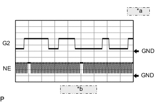
| *a | 2 V/DIV. |
| *b | 20 msec./DIV. |
The correct waveform is as shown.
| ECM Terminal Name | Between G2+ and G2- Between NE+ and NE- |
| Tester Range | 2 V/DIV., 20 msec./DIV. |
| Condition | Idling with warm engine |
MONITOR DESCRIPTION
When the sensor output voltage remains at less than 0.3 V, or higher than 4.7 V, the ECM stores a DTC.
CONFIRMATION DRIVING PATTERN
| DTC No. | DTC Detection Drive Pattern |
|---|---|
| P0337 | Ignition switch ON for 4 seconds or more |
| P0338 |
CAUTION / NOTICE / HINT
Note
After replacing the ECM, the new ECM needs registration (Click here ) and initialization Click here.
Tech Tips
Read freeze frame data using the GTS. Freeze frame data records the engine condition when malfunctions are detected. When troubleshooting, freeze frame data can help determine if the vehicle was moving or stationary, if the engine was warmed up or not, and other data from the time the malfunction occurred.
PROCEDURE
-
CHECK DTC OUTPUT
-
Connect the GTS to the DLC3.
-
Turn the ignition switch to ON and turn the GTS on.
-
Enter the following menus: Powertrain / Engine and ECT / Trouble Codes.
-
Record any output DTC(s).
Powertrain > Engine and ECT > Trouble Codes -
Clear the DTCs.
Powertrain > Engine and ECT > Clear DTCs -
Turn the ignition switch off for 30 seconds or more.
-
Disconnect the crankshaft position sensor connector.
-
Turn the ignition switch to ON for 4 seconds or more.
-
Enter the following menus: Powertrain / Engine and ECT / Trouble Codes.
-
Check whether the DTC changes when the connector is disconnected and connected.
Powertrain > Engine and ECT > Trouble CodesResult Result Proceed to DTC does not change A DTC changes B
B 
GO TO STEP 5 Click here
A 
-
-
CHECK ECM (CRANKSHAFT POSITION SENSOR VOLTAGE)
-
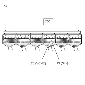
*a Component with harness connected
(ECM)
Measure the voltage according to the value(s) in the table below.
Standard Voltage Tester Connection Switch Condition Specified Condition C60-20 (VCNE) - C60-19 (NE-) Ignition switch ON 4.5 to 5.5 V Result Proceed to OK NG
NG
REPLACE ECM Click here
OK
-
-
CHECK HARNESS AND CONNECTOR (CRANKSHAFT POSITION SENSOR - ECM)
-
Disconnect the crankshaft position sensor connector.
-
Disconnect the ECM connector.
-
Measure the resistance according to the value(s) in the table below.
Standard Resistance Tester Connection Condition Specified Condition Z1-1 (NE+) - C60-28 (NE+) Always Below 1 Ω Z1-2 (NE-) - C60-19 (NE-) Always Below 1 Ω Z1-1 (NE+) or C60-28 (NE+) - Body ground and other terminals Always 10 kΩ or higher Z1-2 (NE-) or C60-19 (NE-) - Body ground and other terminals Always 10 kΩ or higher -
Reconnect the crankshaft position sensor connector.
Result Proceed to OK NG
NG
REPAIR OR REPLACE HARNESS OR CONNECTOR Click here
OK
-
-
CHECK ECM (CHECK RESISTANCE)
-
Disconnect the crankshaft position sensor connector.
-
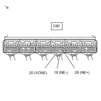
*a Component with harness connected
(ECM)
Measure the resistance according to the value(s) in the table below.
Standard Resistance Tester Connection Switch Condition Specified Condition C60-20 (VCNE) - C60-28 (NE+) Ignition switch off No short or open circuit C60-28 (NE+) - C60-19 (NE-) Ignition switch off No short or open circuit -
Reconnect the crankshaft position sensor connector.
Result Proceed to OK NG
NG
GO TO STEP 7 Click here
OK
-
-
REPLACE CRANKSHAFT POSITION SENSOR
-
Replace the crankshaft position sensor.
Result Proceed to NEXT
NEXT
GO TO STEP 8 Click here
-
-
REPAIR OR REPLACE HARNESS OR CONNECTOR
-
Repair or replace the harness or connector.
Result Proceed to NEXT
NEXT
GO TO STEP 8 Click here
-
-
REPLACE ECM
-
Replace the ECM.
Result Proceed to NEXT
NEXT
-
-
CONFIRM WHETHER MALFUNCTION HAS BEEN SUCCESSFULLY REPAIRED
-
Connect the GTS to the DLC3.
-
Turn the ignition switch to ON.
-
Turn the GTS on.
-
Clear the DTCs.
Powertrain > Engine and ECT > Clear DTCs -
Turn the ignition switch off for 30 seconds or more.
-
Turn the ignition switch to ON for 4 seconds or more.
-
Enter the following menus: Powertrain / Engine and ECT / Trouble Codes.
-
Confirm that the DTC is not output.
Powertrain > Engine and ECT > Trouble CodesResult Proceed to NEXT
NEXT 
END
-