ELECTRONIC CONTROLLED AUTOMATIC TRANSMISSION SYSTEM (for 1KD-FTV), Diagnostic DTC:U0100
| DTC Code | DTC Name |
|---|---|
| U0100 | Lost Communication with ECM / PCM "A" |
DESCRIPTION
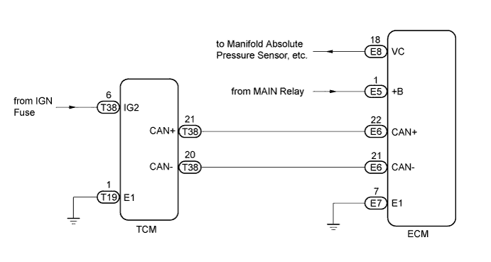
The Transmission Control Module (TCM) and ECM perform 2-way communications with each other via the Controller Area Network (CAN). The TCM sends signals to the ECM concerning required engine rpm, required engine torques, warning indicators in the combination meter, DTCs and other data. The ECM sends signals to the TCM concerning engine rpm, opening angles of the throttle valve, temperature of the intake air and engine coolant, engine torques, and other data.
If the TCM cannot communicate with the ECM, the TCM will conclude that there is a malfunction in the CAN system, illuminate the MIL and set a DTC.
| DTC No. | DTC Detection Condition | Trouble Area |
|---|---|---|
| U0100 | No communication from ECM continues |
|
WIRING DIAGRAM
INSPECTION PROCEDURE
Tech Tips
Read freeze frame data using the intelligent tester. Freeze frame data records the engine conditions when a malfunction is detected. When troubleshooting, freeze frame data can help determine if the vehicle was moving or stationary, if the engine was warmed up or not, and other data from the time the malfunction occurred.
Note
If the ECM is replaced, the new ECM needs initialization.
PROCEDURE
-
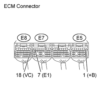
CHECK ECM (VC, +B VOLTAGE, E1 GROUND)
-
Measure the voltage and resistance of the ECM connectors.
Standard Voltage Tester Connection Switch Condition Specified Condition E5-1 (+B) - Body ground Ignition switch ON 9 to 14 V E8-18 (VC) - Body ground Ignition switch ON 4.5 to 5.5 V Standard Resistance Tester Connection Condition Specified Condition E7-7 (E1) - Body ground Always Below 1 Ω
NG 
INSPECT +B, E1 CIRCUIT (ECM POWER SOURCE CIRCUIT OR VC CIRCUIT)
OK 
-
-
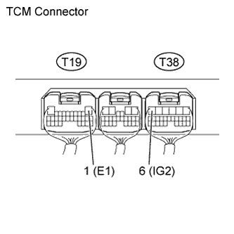
CHECK TCM (IG2 VOLTAGE, E1 GROUND)
-
Measure the voltage and resistance of the TCM connectors.
Standard Voltage Tester Connection Switch Condition Specified Condition T38-6 (IG2) - Body ground Ignition switch ON 9 to 14 V Standard Resistance Tester Connection Condition Specified Condition T19-1 (E1) - Body ground Always Below 1 Ω
NG
INSPECT IG2, E1 CIRCUIT (TCM POWER SOURCE CIRCUIT)
OK
-
-
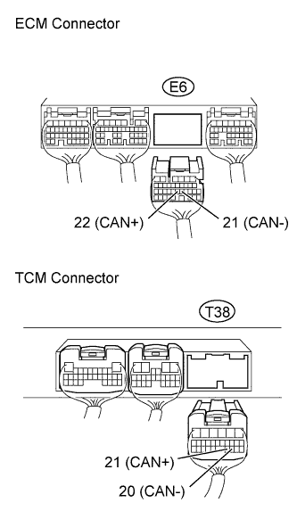
CHECK WIRE HARNESS (ECM - TCM)
-
Disconnect the E6 ECM connector.
-
Disconnect the T38 TCM connector.
-
Measure the resistance of the wire harness side connectors.
Standard Resistance Tester Connection Condition Specified Condition E6-22 (CAN+) - T38-21 (CAN+) Always Below 1 Ω E6-21 (CAN-) - T38-20 (CAN-) Always Below 1 Ω E6-22 (CAN+) or T38-21 (CAN+) - Body ground Always 10 kΩ or higher E6-21 (CAN-) or T38-20 (CAN-) - Body ground Always 10 kΩ or higher
NG
REPAIR OR REPLACE HARNESS AND CONNECTOR
OK
-
-
CONFIRM DTC
-
Clear the DTC.
-
Replace the TCM.
Tech Tips
Replace the TCM with a TCM from a normally functioning vehicle of the same model.
-
Start the engine.
-
Read the DTCs.
Result Result Proceed to U0100 is output A U0100 is not output B
B
REPLACE TCM
A 
REPLACE ECM
-