SHIFT PADDLE SWITCH INSPECTION
PROCEDURE
INSPECT TRANSMISSION SHIFT SWITCH ASSEMBLY
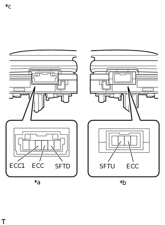
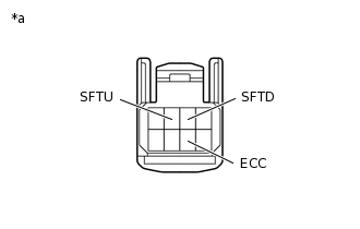
*a
for LH
*b
for RH
*c
Component without wire harness connected
(Transmission Shift Switch Assembly)
Measure the resistance according to the value(s) in the table below.
Standard Resistance
Table 1. for LH Tester Connection
Shift Position
Specified Condition
SFTD - ECC
"-" shift paddle operated and held (down-shift)
Below 2.5 Ω
SFTD - ECC1
"-" shift paddle operated and held (down-shift)
Below 2.5 Ω
SFTD - ECC
"-" shift paddle not operated (down-shift)
1 MΩ or higher
SFTD - ECC1
"-" shift paddle not operated (down-shift)
1 MΩ or higher
Table 2. for RH Tester Connection
Shift Position
Specified Condition
SFTU - ECC
"+" shift paddle operated and held (up-shift)
Below 2.5 Ω
SFTU - ECC
"+" shift paddle not operated (up-shift)
1 MΩ or higher
If the result is not as specified, replace the transmission shift switch assembly.
INSPECT NO. 1 SWITCH WIRE
Connect the No. 1 switch wire connector to the transmission shift switch assembly.
Disconnect the steering pad switch connector from the No. 1 switch wire.
-
*a
Component without wire harness connected
(No. 1 Switch Wire)
Measure the resistance according to the value(s) in the table below.
Standard Resistance
Tester Connection
Switch Condition
Specified Condition
SFTD - ECC
"-" shift paddle operated and held (down-shift)
Below 2.5 Ω
SFTU - ECC
"+" shift paddle operated and held (up-shift)
Below 2.5 Ω
SFTD - ECC
"-" shift paddle not operated (down-shift)
1 MΩ or higher
SFTU - ECC
"+" shift paddle not operated (up-shift)
1 MΩ or higher