SFI SYSTEM, Diagnostic DTC:P15EA12 and P15EA14
| DTC Code | DTC Name |
|---|---|
| P15EA12 | Oil Jet Control Valve Circuit Short to Battery |
| P15EA14 | Oil Jet Control Valve Circuit Short to Ground or Open |
DESCRIPTION
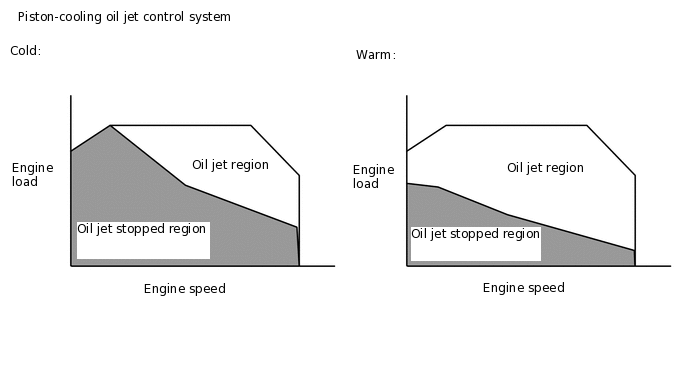
The piston-cooling oil jet control system uses the oil pressure switching valve assembly to start and stop the operation of the oil jets.
When the oil pressure switching valve assembly operates, oil pressure from the oil pressure switching valve assembly closes the relief valve, which shuts off the oil path between the oil pump and oil jet and stops the operation of the oil jets. This reduces fuel dilution during low-temperature starting and improves the piston heating to reduce friction and suppress the generation of deposits. When the oil pressure switching valve assembly is inoperative, oil pressure from the oil pressure switching valve assembly is cut and the relief valve opens. This opens the oil path between the oil pump and oil jet and starts the oil jet to cool and lubricate the pistons.
DTC No. |
Detection Item |
DTC Detection Condition |
Trouble Area |
MIL |
Memory |
Note |
|---|---|---|---|---|---|---|
P15EA12 |
Oil Jet Control Valve Circuit Short to Battery |
Short in oil pressure switching valve assembly circuit and power supply circuit (1 trip detection logic). |
|
Does not come on |
DTC stored |
SAE Code: P15EC |
P15EA14 |
Oil Jet Control Valve Circuit Short to Ground or Open |
Open or short in pressure discharge valve assembly circuit (1 trip detection logic). |
|
Does not come on |
DTC stored |
SAE Code: P15EB |
MONITOR DESCRIPTION
The ECM monitors the output voltage of the oil pressure switching valve assembly while it is operating. If a continuous mismatch occurs between the ECM control value and the output voltage, the ECM determines there is a malfunction and stores a DTC.
CONFIRMATION DRIVING PATTERN
Connect the GTS to the DLC3.
Turn the ignition switch to ON and turn the GTS on.
Clear the DTCs (even if no DTCs are stored, perform the clear DTC procedure).
Turn the ignition switch off and wait for at least 30 seconds.
Turn the ignition switch to ON and turn the GTS on.
Start the engine.
Idle the engine for 30 seconds [A].
Enter the following menus: Powertrain / Engine / Trouble Codes [B].
Read the pending DTCs.
Tip:If a pending DTC is output, the system is malfunctioning.
If a pending DTC is not output, perform the following procedure.
Enter the following menus: Powertrain / Engine / Utility / All Readiness.
Input the DTC: P15EA12 or P15EA14.
Check the DTC judgment result.
GTS Display
Description
NORMAL
DTC judgment completed
System normal
ABNORMAL
DTC judgment completed
System abnormal
INCOMPLETE
DTC judgment not completed
Perform driving pattern after confirming DTC enabling conditions
N/A
Unable to perform DTC judgment
Number of DTCs which do not fulfill DTC preconditions has reached ECU memory limit
Tip:If the judgment result shows NORMAL, the system is normal.
If the judgment result shows ABNORMAL, the system has a malfunction.
If the judgment result shows INCOMPLETE or N/A, perform steps [A] and [B] again.
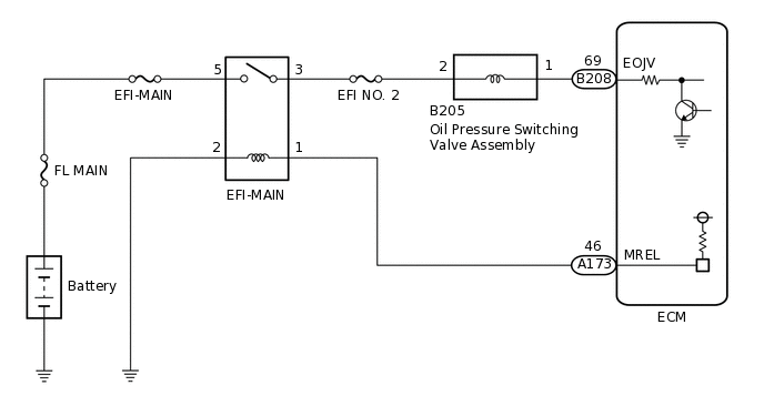
WIRING DIAGRAM
CAUTION / NOTICE / HINT
Inspect the fuses for circuits related to this system before performing the following procedure.
Read freeze frame data using the GTS. The ECM records vehicle and driving condition information as freeze frame data the moment a DTC is stored. When troubleshooting, freeze frame data can help determine if the vehicle was moving or stationary, if the engine was warmed up or not, if the air fuel ratio was lean or rich, and other data from the time the malfunction occurred.
PROCEDURE
CHECK ENGINE OIL LEVEL
Check the engine oil level.
Check the state of the oil level warning light (indicator).
Result
Result
Proceed to
Engine oil level is low and oil level warning light (indicator) is illuminated
A
Engine oil level is within the specified range and oil level warning light (indicator) is not illuminated
B
Tip:If the oil level warning light (indicator) is not illuminated even though the engine oil level is lower than the Low mark, or the oil level warning light (indicator) is illuminated even though the engine oil level is within the specified range, inspect the oil level sensor and related parts.
B INSPECT OIL PUMP RELIEF VALVE HOUSING ASSEMBLY (OIL PRESSURE SWITCHING VALVE OPERATION)Click here
INSPECT FOR ENGINE OIL LEAK
Check for engine oil leaks.
OK
There are no engine oil leaks.
Tip:If there are engine oil leaks, perform repairs.
Result
Proceed to
NEXT
ADD ENGINE OIL
Add engine oil.
Note:Do not add engine oil to above the full level mark.
Result
Proceed to
NEXT
NEXT INSPECT OIL PUMP RELIEF VALVE HOUSING ASSEMBLY (OIL PRESSURE SWITCHING VALVE OPERATION)Click here
INSPECT OIL PUMP RELIEF VALVE HOUSING ASSEMBLY (OIL PRESSURE SWITCHING VALVE OPERATION)
Connect the GTS to the DLC3.
Start the engine.
Tip:Make sure the engine coolant temperature is 70°C (158°F) or less.
Turn the GTS on.
Enter the following menus: Powertrain / Engine / Utility / Engine Oil Jet Control Check.
Powertrain > Engine > Utility
Tester Display
Engine Oil Jet Control Check
According to the display on the GTS, read the Data List and calculate the difference between the values of "Valve OFF: Hi Oil press" and "Valve ON: Low Oil press".
OK
30 kPa (gauge) or higher
Result
Proceed to
OK
NG
INSPECT OIL PUMP RELIEF VALVE HOUSING ASSEMBLY (OIL PRESSURE SWITCHING VALVE ASSEMBLY)
Inspect the oil pressure switching valve assembly.
Result
Proceed to
OK
NG
CHECK TERMINAL VOLTAGE (POWER SOURCE OF OIL PRESSURE SWITCHING VALVE ASSEMBLY)
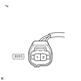
*a
Front view of wire harness connector
(to Oil Pressure Switching Valve Assembly)
Disconnect the oil pressure switching valve assembly connector.
Turn the ignition switch to ON.
Measure the voltage according to the value(s) in the table below.
Standard Voltage
Tester Connection
Condition
Specified Condition
B205-2 - Body ground
Ignition switch ON
11 to 14 V
Result
Proceed to
OK
NG
NG REPAIR OR REPLACE HARNESS OR CONNECTOR (EFI-MAIN RELAY - OIL PRESSURE SWITCHING VALVE ASSEMBLY)
CHECK HARNESS AND CONNECTOR (OIL PRESSURE SWITCHING VALVE ASSEMBLY - ECM)
Disconnect the oil pressure switching valve assembly connector.
Disconnect the ECM connector.
Measure the resistance according to the value(s) in the table below.
Standard Resistance
Tester Connection
Condition
Specified Condition
B205-1 - B208-69 (EOJV)
Always
Below 1 Ω
B205-1 or B208-69 (EOJV) - Body ground and other terminals
Always
10 kΩ or higher
Result
Proceed to
OK
NG
NG REPAIR OR REPLACE HARNESS OR CONNECTOR
CHECK WHETHER DTC OUTPUT RECURS (DTC P15EA12 OR P15EA14)
Connect the GTS to the DLC3.
Turn the ignition switch to ON.
Turn the GTS on.
Clear the DTCs.
Powertrain > Engine > Clear DTCs
Turn the ignition switch off and wait for at least 30 seconds.
Start the engine.
Turn the GTS on.
Drive the vehicle in accordance with the driving pattern described in Confirmation Driving Pattern.
Enter the following menus: Powertrain / Engine / Utility / All Readiness.
Powertrain > Engine > Utility
Tester Display
All Readiness
Input the DTC: P15EA12 or P15EA14.
Check the DTC judgment result.
Result
Result
Proceed to
NORMAL
(DTCs are not output)
A
ABNORMAL
(DTC P15EA12 or P15EA14 is output)
B
A END