ENGINE UNIT REASSEMBLY
PROCEDURE
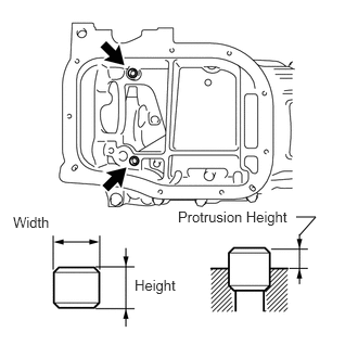
INSTALL STIFFENING CRANKCASE RING PIN
 Note:
Note:It is not necessary to remove a ring pin unless it is being replaced.
Using a plastic-faced hammer, tap in 2 new ring pins until they stop.
Standard Ring Pin
Item
Protrusion Height
Height
Width
Ring pin
3.0 mm (0.118 in.)
11 mm (0.433 in.)
8 mm (0.315 in.)
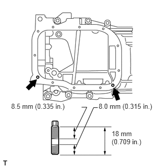
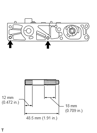
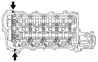
INSTALL STIFFENING CRANKCASE STUD BOLT
 Note:
Note:If a stud bolt is deformed or the threads are damaged, replace it.
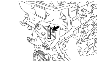
Using an E6 "TORX" socket wrench, install the stud bolts as shown in the illustration.
5.0 N*m
51 kgf*cm
44 in.*lbf
INSTALL STIFFENING CRANKCASE ASSEMBLY
-
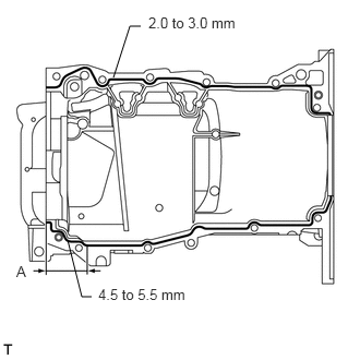
Apply seal packing in a continuous line as shown in the illustration.
Seal packing
Toyota Genuine Seal Packing Black, Three bond 1207B or equivalent
Standard Seal Diameter
Item
Specified Condition
Continuous Line
2.0 to 3.0 mm (0.0787 to 0.118 in.)
A
4.5 to 5.5 mm (0.177 to 0.217 in.)
Application Length A
56 mm (2.20 in.)
Note:Remove any oil from the contact surfaces.
Install the crankcase within 3 minutes and tighten the bolts within 15 minutes after applying seal packing.
Do not start the engine for at least 2 hours after installing the stiffening crankcase assembly.
-
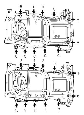
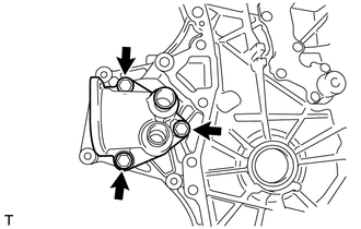
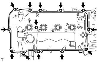
Install the stiffening crankcase with the 11 bolts in the sequence shown in the illustration.
21 N*m
214 kgf*cm
15 ft.*lbf
Bolt Length
Item
Specified Condition
Bolt A
138 mm (5.43 in.)
Bolt B
35 mm (1.38 in.)
Bolt C
70 mm (2.76 in.)
Recheck the torque for bolts 1 and 2.
21 N*m
214 kgf*cm
15 ft.*lbf
Wipe off any excess seal packing with a clean piece of cloth.
-
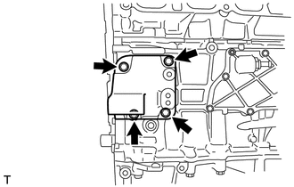
INSTALL OIL PUMP ASSEMBLY
INSTALL NO. 2 OIL PAN SUB-ASSEMBLY
INSTALL OIL PAN DRAIN PLUG
-
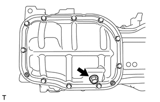
Install a new gasket and the drain plug.
37 N*m
377 kgf*cm
27 ft.*lbf
-
INSTALL ENGINE REAR OIL SEAL
INSTALL NO. 1 TAPER SCREW PLUG
-
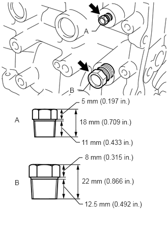
Apply adhesive to 2 or 3 threads of the No. 1 taper screw plug, and install the No. 1 taper screw plug (A).
25 N*m
255 kgf*cm
18 ft.*lbf
Adhesive
Toyota Genuine Adhesive 1344, Three Bond 1344 or equivalent
Note:Install the plug within 3 minutes of applying adhesive.
Do not start the engine within 1 hour of installing the plug.
Apply adhesive to 2 or 3 threads of the No. 1 taper screw plug, and install the No. 1 taper screw plug (B).
43 N*m
438 kgf*cm
32 ft.*lbf
Adhesive
Toyota Genuine Adhesive 1324, Three Bond 1324 or equivalent
Note:Install the plug within 3 minutes of applying adhesive.
Do not start the engine within 1 hour of installing the plug.
-
INSTALL VENTILATION VALVE SUB-ASSEMBLY
INSTALL CYLINDER HEAD GASKET
INSTALL CYLINDER HEAD SUB-ASSEMBLY
INSTALL VALVE STEM CAP
Apply a light coat of engine oil to the valve stem ends.
Install the 16 valve stem caps to the cylinder head.
Note:Do not drop the valve stem caps into the cylinder head.
INSTALL VALVE LASH ADJUSTER ASSEMBLY
Inspect each valve lash adjuster before installing it (Click here).
Install the 16 valve lash adjusters to the cylinder head.
Note:Install the valve lash adjuster to the same place it was removed from.
INSTALL NO. 1 VALVE ROCKER ARM SUB-ASSEMBLY
-
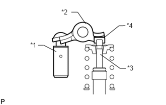
Apply engine oil to the valve lash adjuster tips and valve stem cap ends.
Make sure that the No. 1 valve rocker arms are installed as shown in the illustration.
Table 1. Text in Illustration *1
Lash Adjuster
*2
Valve Rocker Arm
*3
Valve Stem
*4
Valve Stem Cap
-
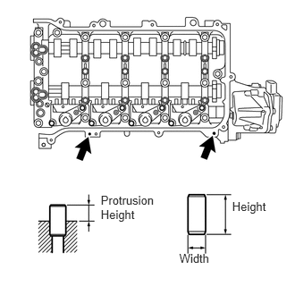
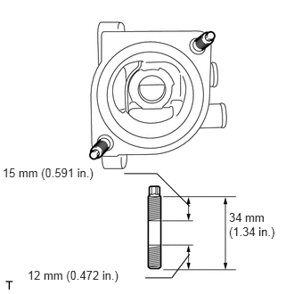
INSTALL CAMSHAFT HOUSING STRAIGHT PIN
 Note:
Note:It is not necessary to remove a straight pin unless it is being replaced.
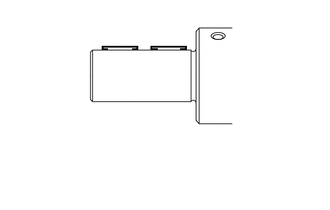
Using a plastic-faced hammer, tap in a new straight pin to the specified protrusion height.
Standard Straight Pin
Item
Protrusion Height
Height
Width
Straight Pin
6.5 to 7.5 mm (0.256 to 0.295 in.)
14 mm (0.551 in.)
6.0 mm (0.236 in.)
INSTALL CAMSHAFT HOUSING STUD BOLT
 Note:
Note:If a stud bolt is deformed or the threads are damaged, replace it.
Using an E7 "TORX" socket wrench, install the camshaft housing stud bolts.
9.5 N*m
97 kgf*cm
84 in.*lbf
INSTALL CONTINUOUSLY VARIABLE VALVE LIFT CONTROLLER ASSEMBLY
-
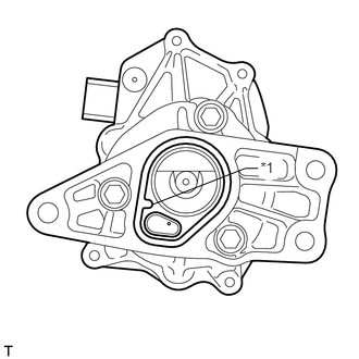
Install a new O-ring to the continuously variable valve lift controller.
Table 2. Text in Illustration *1
Protrusion
Note:Align the protrusion of the O-ring with the protrusion of the continuously variable valve lift controller.
Make sure that the O-ring is not protruding from the groove in the continuously variable valve lift controller.
-
Install the control actuator clip to the control actuator connector.
Tip:When the continuously variable valve lift controller is new, a control actuator connector is attached to it. Remove the control actuator connector before performing these procedures.
Note:Be sure to insert the protrusions of the control actuator clip into the holes in the control actuator connector.
-
Install the valve lift control actuator connector to the valve rocker shaft.
Tip:There are two types of valve lift control actuator connectors. One type is installed by rotating the connector, and the other type can be installed without being rotated.
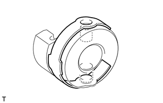
Insert the continuously variable valve lift controller into the camshaft housing.
-
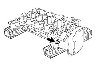
Install the continuously variable valve lift controller to the camshaft housing with the bolt.
18 N*m
184 kgf*cm
13 ft.*lbf
Note:Do not let the O-ring become jammed between parts.
-
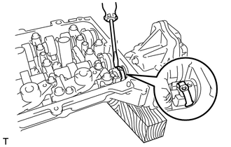
Using a screwdriver, slide the control actuator clip from the control actuator connector.
Slide only the upper part of the control actuator clip as the straight pin may fall if the control actuator clip is completely removed.
Using a screwdriver, lightly pry the control actuator connector and align the hole in the control actuator connector with the hole in the continuously variable valve lift controller.
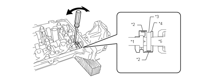
Table 3. Text in Illustration *1
Rocker Shaft
*2
Clip
*3
Straight Pin Hole
*4
Connector
*5
Controller Shaft
Note:Do not forcefully pry the control actuator connector.
Do not damage the camshaft housing or camshaft bearing cap.
-
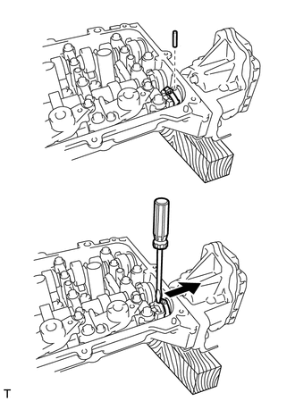
Insert the straight pin into the control actuator connector.
Note:Do not use a tool to insert the straight pin. Insert the straight pin by hand.
Tip:If the straight pin is difficult to insert, insert the straight pin while lightly prying the control actuator connector.
Using a screwdriver, install the control actuator clip to the control actuator connector.
Note:Insert the protrusion of the control actuator clip into the hole in the control actuator connector.
-
INSTALL CAMSHAFT HOUSING SUB-ASSEMBLY
INSTALL CAMSHAFT TIMING EXHAUST GEAR ASSEMBLY
INSTALL CAMSHAFT TIMING GEAR ASSEMBLY
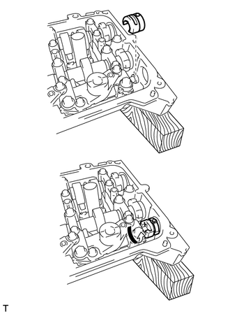
INSTALL CRANKSHAFT TIMING GEAR KEY
-
Using a plastic-faced hammer, tap in the 2 crankshaft timing gear keys.
Tip:Tap in the crankshaft timing gear keys until they contact the crankshaft as shown in the illustration.
-
INSTALL NO. 1 CRANKSHAFT POSITION SENSOR PLATE
-
Install the crankshaft position sensor plate with the "F" mark facing forward.
-
INSTALL NO. 2 CHAIN SUB-ASSEMBLY
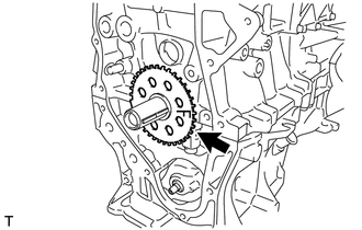
INSTALL CRANKSHAFT TIMING SPROCKET
INSTALL NO. 1 CHAIN VIBRATION DAMPER
SET NO. 1 CYLINDER TO TDC/COMPRESSION
INSTALL CHAIN SUB-ASSEMBLY
INSTALL CHAIN TENSIONER SLIPPER
CHECK NO. 1 CYLINDER TO TDC/COMPRESSION
INSTALL NO. 1 GENERATOR BRACKET
-
Install the generator bracket with the 4 bolts.
24 N*m
245 kgf*cm
18 ft.*lbf
-
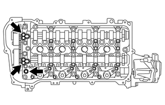
INSTALL WATER INLET HOUSING STUD BOLT
 Note:
Note:If a stud bolt is deformed or the threads are damaged, replace it.
Using an E5 "TORX" socket wrench, install the stud bolts as shown in the illustration.
5.0 N*m
51 kgf*cm
44 in.*lbf
INSTALL WATER INLET HOUSING
-
Install a new gasket and the water inlet housing with the 3 bolts.
21 N*m
214 kgf*cm
15 ft.*lbf
-
INSTALL TIMING CHAIN COVER SUB-ASSEMBLY
INSTALL TIMING CHAIN COVER OIL SEAL
INSTALL ENGINE MOUNTING BRACKET STUD BOLT
 Note:
Note:If a stud bolt is deformed or the threads are damaged, replace it.
Install the stud bolt.
10 N*m
102 kgf*cm
7 ft.*lbf
INSTALL CRANKSHAFT PULLEY
INSTALL NO. 1 CHAIN TENSIONER ASSEMBLY
INSTALL OIL FILTER CAP ASSEMBLY
INSTALL SPARK PLUG TUBE GASKET
-
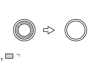
Using a cutter knife, cut off the seal part of the removed gasket.
Table 4. Text in Illustration *1
Part to Cut Off
-
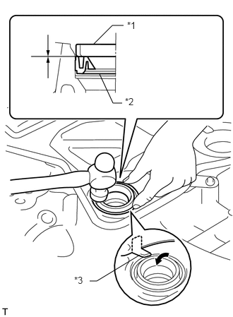
Using a hammer and a plug tube gasket which has had the sealing part cut off, uniformly tap in a new plug tube gasket all the way.
Table 5. Text in Illustration *1
Plug Tube Gasket without Sealing Part
*2
New Plug Tube Gasket
*3
Claw
Tip:If a plug tube gasket that will be used to install a new gasket is deformed and cannot be positioned on a new gasket, correct the deformation using pliers.
Note:Keep the lip free of foreign matter.
Do not tap in the plug tube gasket at an angle.
Return the claws of the ventilation baffle plate to their original positions.
-
INSTALL CYLINDER HEAD COVER GASKET
-
Install a new cylinder head cover gasket to the cylinder head cover.
Note:Remove any oil from the contact surfaces.
-
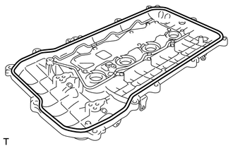
INSTALL CYLINDER HEAD COVER SUB-ASSEMBLY
-
Install 3 new gaskets to the camshaft bearing cap.
-
Apply seal packing as shown in the illustration.
Seal packing
Toyota Genuine Seal Packing Black, Three Bond 1207B or equivalent
Standard diameter
4.0 mm (0.157 in.)
Note:Remove any oil from the contact surfaces.
Install the cylinder head cover sub-assembly within 3 minutes and tighten the bolts within 15 minutes after applying seal packing.
Do not start the engine for at least 2 hours after the installation.
-
Install the cylinder head cover with a new seal washer and the 13 bolts.
10 N*m
102 kgf*cm
7 ft.*lbf
-
INSTALL ENGINE OIL PRESSURE SWITCH ASSEMBLY
INSTALL ENGINE COOLANT TEMPERATURE SENSOR
-
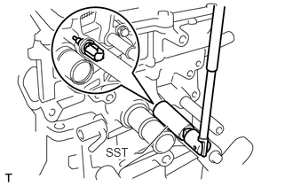
Using SST, install a new gasket and the engine coolant temperature sensor.
09817-33190
20 N*m
204 kgf*cm
15 ft.*lbf
-
INSTALL KNOCK SENSOR
-
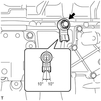
Install the knock sensor with the bolt.
21 N*m
214 kgf*cm
15 ft.*lbf
Note:Make sure that the knock sensor is in the correct position.
-
INSTALL CRANKSHAFT POSITION SENSOR
-
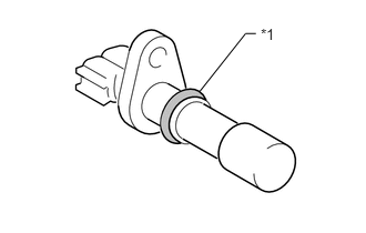
Apply a light coat of engine oil to the O-ring of the sensor.
Table 6. Text in Illustration *1
O-Ring
-
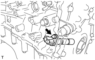
Install the crankshaft position sensor with the bolt.
10 N*m
102 kgf*cm
7 ft.*lbf
-
INSTALL CAMSHAFT TIMING OIL CONTROL VALVE ASSEMBLY
-
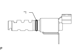
Apply a light coat of engine oil to 2 new O-rings and install them to the camshaft timing oil control valves.
Table 7. Text in Illustration *1
New O-Ring
-
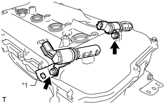
Install the 2 camshaft timing oil control valves and bracket with the 2 bolts.
Table 8. Text in Illustration *1
Bracket
10 N*m
102 kgf*cm
7 ft.*lbf
Note:Do not allow foreign matter to contact the oil seal face of the oil control valve (connecting surface with cylinder head cover).
Be careful that the O-ring is not cracked or moved out of place when installing the oil control valve.
-
INSTALL CAMSHAFT POSITION SENSOR
-
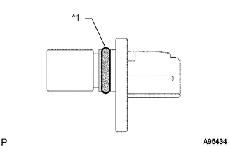
Apply a light coat of engine oil to the O-rings of the sensors.
Table 9. Text in Illustration *1
O-Ring
-
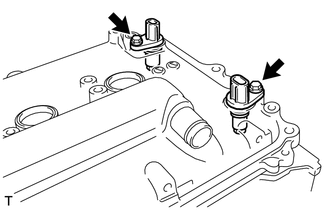
Install the 2 camshaft position sensors with the 2 bolts.
10 N*m
102 kgf*cm
7 ft.*lbf
Note:Make sure that the O-ring is not cracked or jammed when installing the sensor.
-
INSTALL SPARK PLUG
INSTALL ENGINE COVER JOINT
-
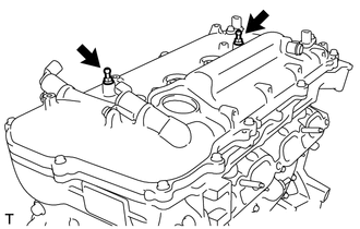
Install the 2 engine cover joints.
10 N*m
102 kgf*cm
7 ft.*lbf
-
INSTALL OIL FILLER CAP GASKET
-
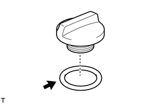
Install the gasket to the oil filler cap.
-
INSTALL OIL FILLER CAP SUB-ASSEMBLY
-
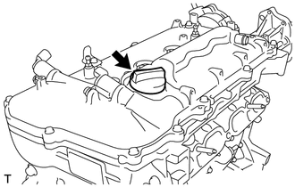
Install the oil filler cap.
-