ENGINE UNIT REASSEMBLY

PROCEDURE
-
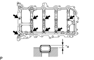
INSTALL STRAIGHT PIN
Note
It is not necessary to remove the straight pin unless they are being replaced.
-
*a Protrusion Height Using a plastic hammer, install 2 new straight pins.
Standard Protrusion Height 5.0 to 7.0 mm (0.197 to 0.276 in.)
-
-
INSTALL RING PIN
Note
It is not necessary to remove the ring pins unless they are being replaced.
-
Stiffening crankcase assembly lower side:
-
*a Protrusion Height Using a plastic hammer, install 2 new ring pins.
Standard Protrusion Height 4.3 to 5.3 mm (0.169 to 0.209 in.)
-
-
Camshaft housing sub-assembly lower side:
-
*a Protrusion Height Using a plastic hammer, install 8 new ring pins.
Standard Protrusion Height 2.7 to 3.3 mm (0.106 to 0.130 in.)
-
-
-
INSTALL STUD BOLT
Note
If a stud bolt is deformed or its threads are damaged, replace it.
-
Timing chain cover sub-assembly front side:
-
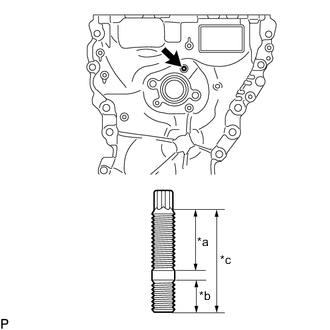
*a 16 mm (0.630 in.) *b 9 mm (0.354 in.) *c 27 mm (1.06 in.) Using an E6 "TORX" socket wrench, install the stud bolt.
- Torque:
- 4.0 N*m { 41 kgf*cm, 35 in.*lbf }
-
-
Stiffening crankcase assembly lower and LH sides:
-
Using E5 and E8 "TORX" socket wrenches, install the 4 stud bolts.
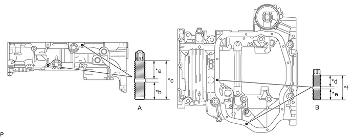
*a 14 mm (0.551 in.) *b 13 mm (0.512 in.) *c 29 mm (1.14 in.) *d 8.5 mm (0.335 in.) *e 8.0 mm (0.315 in.) *f 18 mm (0.709 in.) - Torque:
- Stud Bolt (A)
- 6.5 N*m { 66 kgf*cm, 58 in.*lbf }
- Stud Bolt (B)
- 4.0 N*m { 41 kgf*cm, 35 in.*lbf }
-
-
Camshaft housing sub-assembly front side:
-
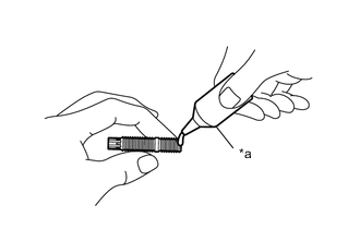
*a Adhesive When reusing the stud bolt:
Apply adhesive to the threads (camshaft housing sub-assembly side) of the stud bolt.
Adhesive Toyota Genuine Adhesive 1324, Three Bond 1324 or equivalent Note
Install the stud bolt within 3 minutes of applying adhesive.
-
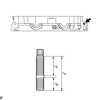
*a 20 mm (0.787 in.) *b 13 mm (0.512 in.) *c 35 mm (1.38 in.) Using an E8 "TORX" socket wrench, install the stud bolt.
- Torque:
- 6.5 N*m { 66 kgf*cm, 58 in.*lbf }
-
-
Camshaft housing sub-assembly upper side:
-
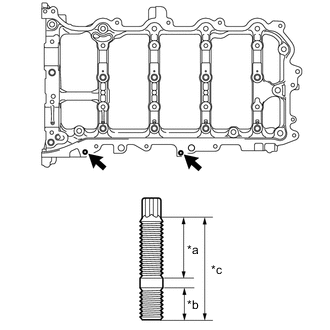
*a 16 mm (0.630 in.) *b 9 mm (0.354 in.) *c 27 mm (1.06 in.) Using an E6 "TORX" socket wrench, install the 2 stud bolts.
- Torque:
- 4.0 N*m { 41 kgf*cm, 35 in.*lbf }
-
-
Cylinder head cover sub-assembly upper side:
-
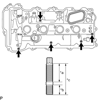
*a 16 mm (0.630 in.) *b 9 mm (0.354 in.) *c 27 mm (1.06 in.) Using an E6 "TORX" socket wrench, install the 5 stud bolts.
- Torque:
- 4.0 N*m { 41 kgf*cm, 35 in.*lbf }
-
-
-
SET ENGINE BALANCER ASSEMBLY
-
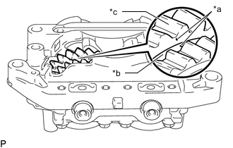
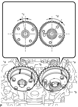
*a Match Mark *b No. 2 Balance Shaft Driven Gear *c No. 1 Balance Shaft Driven Gear Make sure that the match marks on the No. 1 balance shaft driven gear and No. 2 balance shaft driven gear are aligned.
-
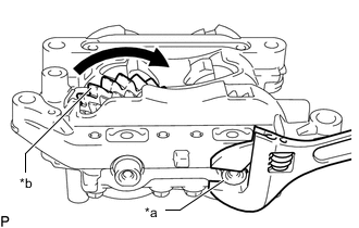
*a No. 2 Balance Shaft *b No. 1 Balance Shaft Driven Gear If the match marks are not aligned, hold the No. 2 balance shaft with a wrench, and rotate the No. 1 balance shaft as shown in the illustration to align the match marks.
-
-
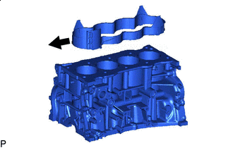
INSTALL STIFFENING CRANKCASE ASSEMBLY
-
Clean the bolts and bolt holes.
-
Clean the contact surfaces of the cylinder block sub-assembly and stiffening crankcase assembly.
-
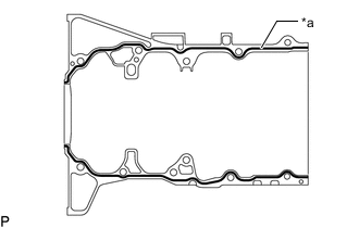
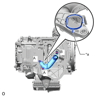
*a Seal Packing Apply seal packing in a continuous line as shown in the illustration.
Seal Packing Toyota Genuine Seal Packing Black, Three Bond 1207B or equivalent Standard Seal Packing Diameter 2.5 to 3.5 mm (0.0984 to 0.138 in.) Note
-
Install the stiffening crankcase assembly within 3 minutes and tighten the bolts within 10 minutes of applying seal packing.
-
Do not add engine oil for at least 2 hours after installation.
-
Do not start the engine for at least 2 hours after installation.
-
-
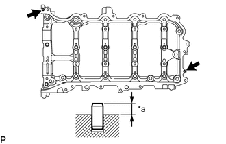
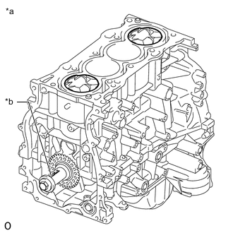
Align the straight pins on the cylinder block sub-assembly with the holes in the stiffening crankcase assembly, and then install the stiffening crankcase assembly to the cylinder block sub-assembly.
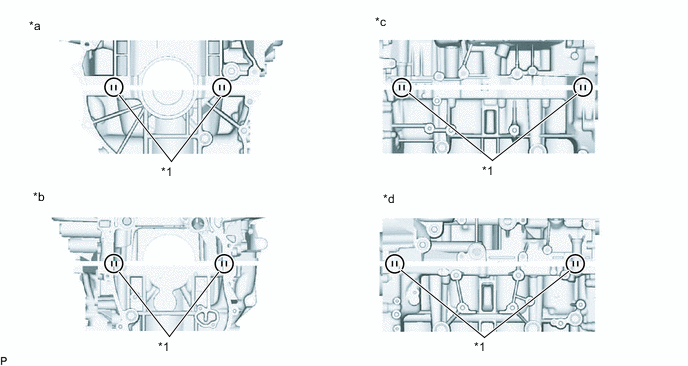
*1 Straight Pin - - *a Rear Side *b Front Side *c RH Side *d LH Side -
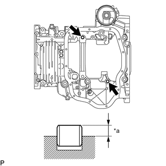
After installing the stiffening crankcase assembly, check that the seal packing has seeped out at the areas shown in the illustration.
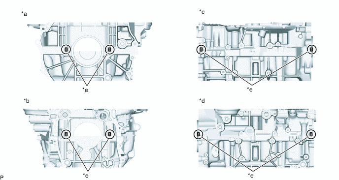
*a Rear Side *b Front Side *c RH Side *d LH Side *e Areas where the Seal Packing Seeps Out - - Note
If the seal packing does not seep out, reapply seal packing and install the stiffening crankcase assembly.
-
Wipe off the seal packing that has seeped out at the joint of the stiffening crankcase assembly and the cylinder block sub-assembly.
Note
Wipe off the seal packing within 5 minutes of installing the stiffening crankcase assembly.
-
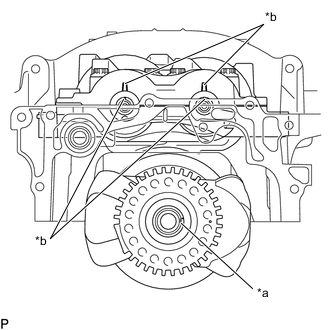
*a Crankshaft Pulley Set Crankshaft Key Groove *b Timing Mark Align the crankshaft pulley set crankshaft key groove, timing marks on the balance shaft and balance shaft housing as shown in the illustration, and then set the engine balancer assembly to the stiffening crankcase assembly.
-
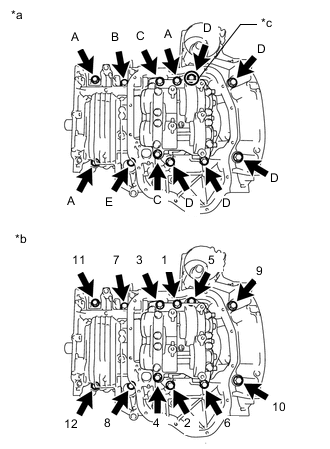
*a Bolt Type *b Tightening Order *c Apply Adhesive Apply adhesive to the threads portion of one of the bolts (D).
Adhesive Toyota Genuine Adhesive 1344, Three Bond 1344 or equivalent Note
Install the bolt within 3 minutes of applying adhesive.
-
Temporarily install the stiffening crankcase assembly with the 12 bolts.
-
Tighten the 12 bolts in the order shown in the illustration.
- Torque:
- Bolt (A)
- 24 N*m { 245 kgf*cm, 18 ft.*lbf }
- except Bolt (A)
- 43 N*m { 438 kgf*cm, 32 ft.*lbf }
Bolt Length Item Length Diameter Bolt (A) 65 mm (2.56 in.) 8.0 mm (0.315 in.) Bolt (B) 65 mm (2.56 in.) 10 mm (0.394 in.) Bolt (C) 140 mm (5.51 in.) Bolt (D) 125 mm (4.92 in.) Bolt (E) 35 mm (1.38 in.) -
Temporarily install the crankshaft pulley set bolt.
-
*a No. 1 Cylinder TDC/Compression *b Crankshaft Pulley Set Crankshaft Key Groove Rotate the crankshaft clockwise to set the No. 1 cylinder to TDC/compression.
-
Remove the crankshaft pulley set bolt.
-
-
INSTALL NO. 1 OIL PAN BAFFLE PLATE
-
Install the No. 1 oil pan baffle plate to the engine balancer assembly with the 4 bolts.
- Torque:
- 10 N*m { 102 kgf*cm, 7 ft.*lbf }
-
-
INSTALL OIL STRAINER SUB-ASSEMBLY
-
Apply a light coat of engine oil to a new gasket.
-
*a Protrusion Align the protrusion of the gasket with the cutout of the oil strainer sub-assembly, and install the gasket to the oil strainer sub-assembly.
-
Temporarily install the oil strainer sub-assembly with the 3 bolts.
-
Tighten the 2 bolts (A).
- Torque:
- 10 N*m { 102 kgf*cm, 7 ft.*lbf }
-
Tighten the bolt (B).
- Torque:
- 10 N*m { 102 kgf*cm, 7 ft.*lbf }
-
-
INSTALL OIL PAN SUB-ASSEMBLY
-
Clean the contact surfaces of the oil pan sub-assembly and stiffening crankcase assembly.
-
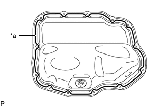
*a Seal Packing Apply seal packing in a continuous line as shown in the illustration.
Seal Packing Toyota Genuine Seal Packing Black, Three Bond 1207B or equivalent Standard Seal Packing Diameter 2.5 to 3.5 mm (0.0984 to 0.138 in.) Note
-
Install the oil pan sub-assembly within 3 minutes and tighten the bolts and nuts within 10 minutes of applying seal packing.
-
Do not add engine oil for at least 2 hours after installation.
-
Do not start the engine for at least 2 hours after installation.
-
-
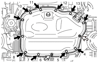

Bolt 
Nut Install the oil pan sub-assembly with the 11 bolts and 2 nuts in several steps in the order shown in the illustration.
- Torque:
- 10 N*m { 102 kgf*cm, 7 ft.*lbf }
-
-
INSTALL OIL PAN DRAIN PLUG
-
Install a new gasket and the oil pan drain plug.
- Torque:
- 40 N*m { 408 kgf*cm, 30 ft.*lbf }
-
-
INSTALL OIL COOLER ASSEMBLY
-
INSTALL ENGINE OIL LEVEL SENSOR
-
INSTALL OIL FILTER CAP ASSEMBLY
-
INSTALL REAR ENGINE OIL SEAL
-
INSTALL CYLINDER BLOCK WATER JACKET SPACER
-
Front of Engine Install the cylinder block water jacket spacer to the cylinder block sub-assembly.
-
-
INSTALL CYLINDER HEAD GASKET
-
INSTALL CYLINDER HEAD SUB-ASSEMBLY
-
INSTALL VALVE STEM CAP
-
INSTALL VALVE LASH ADJUSTER ASSEMBLY
-
INSTALL NO. 1 VALVE ROCKER ARM SUB-ASSEMBLY
-
INSTALL NO. 2 CAMSHAFT BEARING
-
INSTALL NO. 2 CAMSHAFT
-
INSTALL CAMSHAFT
-
INSTALL NO. 1 CAMSHAFT BEARING
-
INSTALL OIL CONTROL VALVE FILTER
-
INSTALL CAMSHAFT BEARING CAP
-
INSTALL CAMSHAFT HOUSING SUB-ASSEMBLY
-
INSTALL OIL PIPE SUB-ASSEMBLY
-
Install the oil pipe sub-assembly to the No. 4 camshaft bearing cap with the bolt.
- Torque:
- 10 N*m { 102 kgf*cm, 7 ft.*lbf }
-
-
INSPECT CAMSHAFT TIMING EXHAUST GEAR ASSEMBLY
-
INSTALL CAMSHAFT TIMING EXHAUST GEAR ASSEMBLY
-
INSPECT CAMSHAFT TIMING GEAR ASSEMBLY
-
INSTALL CAMSHAFT TIMING GEAR ASSEMBLY
-
INSTALL CRANKSHAFT PULLEY SET CRANKSHAFT KEY
-
Install the 2 crankshaft pulley set crankshaft keys to the crankshaft.
-
-
INSTALL CRANKSHAFT TIMING SPROCKET
-
Align the crankshaft timing sprocket groove with the crankshaft pulley set crankshaft key, and install the crankshaft timing sprocket to the crankshaft.
-
-
ADD ENGINE OIL
Note
-
Make sure to add engine oil if the valve lash adjuster assemblies or No. 1 valve rocker arm sub-assemblies were removed.
-
Make sure that the oil passage is filled with engine oil.
-
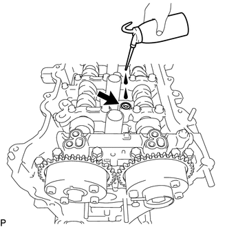
Add 100 cc (6.1 cu. in.) of engine oil into the oil hole shown in the illustration.
-
-
INSTALL NO. 1 CHAIN VIBRATION DAMPER
-
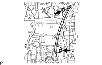
Install the No. 1 chain vibration damper by tightening the 2 bolts in the order shown in the illustration.
- Torque:
- 21 N*m { 214 kgf*cm, 15 ft.*lbf }
-
-
INSTALL CHAIN SUB-ASSEMBLY
-
Temporarily install the crankshaft pulley set bolt.
-
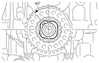
Rotate the crankshaft 40° counterclockwise.
-
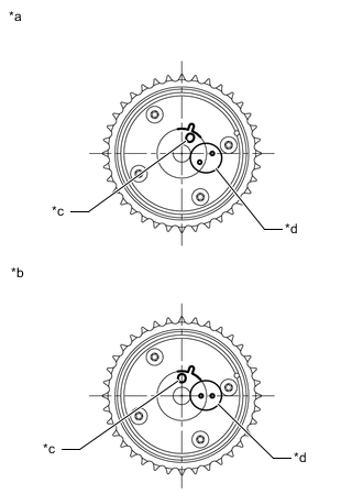
*a Timing Mark *b Identification Groove *c Approximately 7° *d Approximately 32° Check that the timing marks of the camshaft timing gear assembly and camshaft timing exhaust gear assembly are as shown in the illustration.
Tech Tips
The camshaft timing gear assembly and the camshaft timing exhaust gear assembly have both timing marks and identification grooves. Use the timing marks for alignment.
-
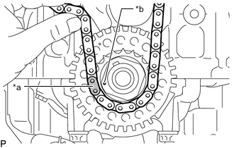
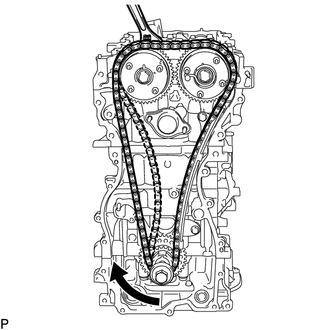
Place the chain sub-assembly onto the camshaft timing gear assembly, camshaft timing exhaust gear assembly and crankshaft timing sprocket.
Tech Tips
-
Make sure the mark plate of the chain sub-assembly faces away from the front of the engine.
-
It is not necessary to install the chain sub-assembly to the teeth of the camshaft timing gear assembly, camshaft timing exhaust gear assembly and crankshaft timing sprocket.
-
-
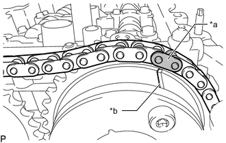
*a Mark Plate (Orange) *b Timing Mark Align the mark plate (orange) of the chain sub-assembly with the timing mark of the camshaft timing exhaust gear assembly and install the chain sub-assembly to the camshaft timing exhaust gear assembly.
-
*a Mark Plate (Yellow) *b Timing Mark Align the mark plate (yellow) of the chain sub-assembly with the timing mark of the crankshaft timing sprocket and install the chain sub-assembly to the crankshaft timing sprocket.
-
*a String Tie the chain sub-assembly with a string above the crankshaft timing sprocket to secure the chain sub-assembly.
-
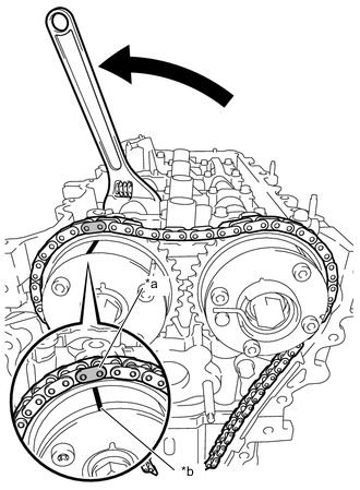
*a Mark Plate (Orange) *b Timing Mark Using a wrench, hold the hexagonal portion of the camshaft and rotate the camshaft counterclockwise to align the timing mark of the camshaft timing gear assembly with the mark plate (orange) of the chain sub-assembly, and install the chain sub-assembly to the camshaft timing gear assembly.
Tech Tips
Hold the camshaft in place with a wrench until the No. 1 chain tensioner assembly is installed.
-
Remove the string above the crankshaft timing sprocket, rotate the crankshaft clockwise, and loosen the chain sub-assembly so that the chain tensioner slipper can be installed.
Note
Make sure that the chain sub-assembly is securely installed.
-
-
INSTALL CHAIN TENSIONER SLIPPER
-
Install the chain tensioner slipper to the cylinder head sub-assembly with the bolt.
- Torque:
- 21 N*m { 214 kgf*cm, 15 ft.*lbf }
-
-
INSTALL NO. 1 CHAIN TENSIONER ASSEMBLY
-
Install a new chain tensioner gasket and the No. 1 chain tensioner assembly to the cylinder block sub-assembly with the 2 bolts.
- Torque:
- 10 N*m { 102 kgf*cm, 7 ft.*lbf }
-
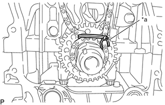
Remove the pin from the stopper plate.
-
*a Lock Pin Released *b Lock Pin Locked *c Pin Hole *d Lock Check Point Rotate the camshaft counterclockwise, and then check that the camshaft timing gear assembly locks at the most retarded position.
Note
If the camshaft timing gear assembly is not locked, make sure to lock it securely.
-
-
INSTALL TIMING CHAIN GUIDE
-
Install the timing chain guide to the No. 1 camshaft bearing cap with the bolt.
- Torque:
- 21 N*m { 214 kgf*cm, 15 ft.*lbf }
-
-
SET NO. 1 CYLINDER TO TDC/COMPRESSION
-
INSTALL TIMING CHAIN COVER PLATE
-
Install a new No. 1 timing belt cover gasket and the timing chain cover plate to the timing chain cover assembly with the 4 bolts.
- Torque:
- 10 N*m { 102 kgf*cm, 7 ft.*lbf }
-
-
INSTALL TIMING CHAIN COVER ASSEMBLY
-
INSTALL TIMING CHAIN COVER OIL SEAL
-
INSTALL CRANKSHAFT PULLEY ASSEMBLY
-
INSTALL CRANKSHAFT POSITION SENSOR
-
INSTALL SPARK PLUG TUBE GASKET
-
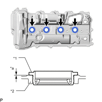
*1 Spark Plug Tube Gasket *2 Cylinder Head Cover Sub-assembly *a 0 mm (0 in.) Install 4 new spark plug tube gaskets to the cylinder head cover sub-assembly as shown in the illustration.
Note
-
Do not install the spark plug tube gaskets at an angle.
-
Keep the lip free from foreign matter.
-
-
-
INSTALL VENTILATION CASE SUB-ASSEMBLY
-
Apply a light coat of engine oil to a new O-ring.
-
*a O-ring Groove *b O-ring Install the O-ring to the ventilation case sub-assembly as shown in the illustration.
Note
Securely install the O-ring into the O-ring groove of the ventilation case sub-assembly.
-
Install the ventilation case sub-assembly to the cylinder head cover sub-assembly with the 2 bolts.
- Torque:
- 10 N*m { 102 kgf*cm, 7 ft.*lbf }
-
Install a new gasket to the ventilation case sub-assembly.
-
-
INSTALL CYLINDER HEAD COVER SUB-ASSEMBLY
-
INSTALL OIL FILLER CAP GASKET
-
Install the oil filler cap gasket to the oil filler cap sub-assembly.
-
-
INSTALL OIL FILLER CAP SUB-ASSEMBLY
-
Install the oil filler cap sub-assembly to the cylinder head cover sub-assembly.
-
-
INSTALL PCV VALVE (VENTILATION VALVE SUB-ASSEMBLY)
-
INSTALL VVT SENSOR
-
INSTALL CAMSHAFT TIMING OIL CONTROL VALVE ASSEMBLY
-
INSTALL ENGINE OIL PRESSURE SWITCH ASSEMBLY
-
INSTALL KNOCK CONTROL SENSOR
-
INSTALL SPARK PLUG
-
INSTALL NO. 4 WATER BY-PASS PIPE
-
Install the No. 4 water by-pass pipe with the 2 bolts.
- Torque:
- 10 N*m { 102 kgf*cm, 7 ft.*lbf }
-
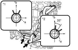
*1 No. 8 Water By-pass Hose *2 No. 7 Water By-pass Hose *a Paint Mark *b Up Connect the No. 7 water by-pass hose and No. 8 water by-pass hose to the oil cooler assembly and slide the 2 clips to secure them.
-
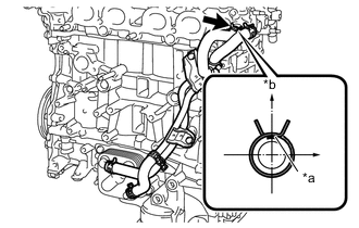
*a Paint Mark *b Up Connect the No. 9 water by-pass hose to the cylinder head sub-assembly and slide the clip to secure it.
-