SFI SYSTEM(w/ Canister Pump Module), Diagnostic DTC:P006D62, P00F762
| DTC Code | DTC Name |
|---|---|
| P006D62 | Barometric Pressure - Turbocharger/Supercharger Inlet Pressure Correlation Bank 1 Signal Compare Failure |
| P00F762 | Barometric Pressure - Turbocharger/Supercharger Inlet Pressure Correlation Bank 2 Signal Compare Failure |
DESCRIPTION
The vacuum sensor assembly is installed upstream of the turbocharger compressor and measures the air inlet duct internal pressure with a built-in sensor.
At engine switch on (IG) or during idling, the vacuum sensor assembly and the atmospheric pressure sensor built into the ECM are at atmospheric pressure and their output match.
| DTC No. | Detection Item | DTC Detection Condition | Trouble Area | MIL | Memory | Note |
|---|---|---|---|---|---|---|
| P006D62 | Barometric Pressure - Turbocharger/Supercharger Inlet Pressure Correlation Bank 1 Signal Compare Failure | Either of the following conditions is met (1 trip detection logic):
|
|
- | DTC stored | SAE: P006D |
| P00F762 | Barometric Pressure - Turbocharger/Supercharger Inlet Pressure Correlation Bank 2 Signal Compare Failure | Either of the following conditions is met (1 trip detection logic):
|
|
- | DTC stored | SAE: P00F7 |
MONITOR DESCRIPTION
At engine switch on (IG) or during idling, if the difference in atmospheric pressure values is the threshold or greater when the output values from the vacuum sensor assembly and the atmospheric pressure sensor built into the ECM are compared, or if the deviation between the air cleaner pressure loss calculated from the atmospheric pressure and vacuum sensor assembly and the air cleaner pressure loss estimated from the mass air flow meter sub-assembly is at the threshold or higher while driving (example: when the intake air volume is 40 gm/sec, the value obtained by subtracting the atmospheric pressure from the vacuum sensor assembly value is larger than 9.27 kPa [1.35 psi]or less than -11.61 kPa [-1.68 psi]), the ECM stores a DTC.
MONITOR STRATEGY
| Frequency of Operation | Continuous |
WIRING DIAGRAM
Refer to DTC P010012 for the mass air flow meter sub-assembly circuit.
Refer to DTC P012A11 for the vacuum sensor assembly circuit.
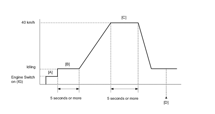
CONFIRMATION DRIVING PATTERN
-
Connect the GTS to the DLC3.
-
Turn the engine switch is on (IG) and turn the GTS on.
-
Clear the DTCs (even if no DTCs are stored, perform the clear DTC procedure).
-
Turn the engine switch off and wait for at least 30 seconds.
-
Turn the engine switch is on (IG) and turn the GTS on [A].
-
Start the engine and wait 5 seconds or more [B].
-
Drive the vehicle at 40 km/h (25 mph) for 5 seconds or more [C].
-
Enter the following menus: Powertrain / Engine / Trouble Codes [D].
-
Read the pending DTCs.
Tech Tips
-
If a pending DTC is output, the system is malfunctioning.
-
If a pending DTC is not output, perform the following procedure.
-
-
Enter the following menus: Powertrain / Engine / Utility / All Readiness.
-
Input the DTC: P006D62 and P00F762.
-
Check the DTC judgment result.
GTS Display Description NORMAL
-
DTC judgment completed
-
System normal
ABNORMAL
-
DTC judgment completed
-
System abnormal
INCOMPLETE
-
DTC judgment not completed
-
Perform driving pattern after confirming DTC enabling conditions
Tech Tips
-
If the judgment result shows NORMAL, the system is normal.
-
If the judgment result shows ABNORMAL, the system has a malfunction.
-
CAUTION / NOTICE / HINT
Tech Tips
-
Read Freeze Frame Data using the GTS. The ECM records vehicle and driving condition information as Freeze Frame Data the moment a DTC is stored. When troubleshooting, Freeze Frame Data can help determine if the vehicle was moving or stationary, if the engine was warmed up or not, if the air fuel ratio was lean or rich, and other data from the time the malfunction occurred.
-
Bank 1 refers to the bank that includes the No. 1 cylinder*.
*: The No. 1 cylinder is the cylinder which is farthest from the transmission.
-
Bank 2 refers to the bank that does not include the No. 1 cylinder.
DTC Suspected Area P006D62 Bank 1 P00F762 Bank 2
PROCEDURE
-
CHECK ANY OTHER DTCS OUTPUT (IN ADDITION TO DTC P006D62 AND/OR P00F762)
-
Connect the GTS to the DLC3.
-
Turn the engine switch on (IG).
-
Turn the GTS on.
-
Enter the following menus: Powertrain / Engine / Trouble Codes.
-
Read the DTCs.
Powertrain > Engine > Trouble CodesResult Result Proceed to DTC P006D62 and/or P00F762 is output A DTC P006D62 and/or P00F762 and other DTCs are output B Tech Tips
If any DTCs other than P006D62 and/or P00F762 are output, troubleshoot those DTCs first.
B 
GO TO DTC CHART Click here
A 
-
-
READ VALUE USING GTS (TURBOCHARGER/SUPERCHARGER INLET PRESSURE BANK1, TURBOCHARGER/SUPERCHARGER INLET PRESSURE BANK2 AND ATMOSPHERIC PRESSURE)
-
Connect the GTS to the DLC3.
-
Turn the engine switch on (IG).
-
Turn the GTS on.
-
Enter the following menus: Powertrain / Engine / Data List / Turbocharger/Supercharger Inlet Pressure Bank1, Turbocharger/Supercharger Inlet Pressure Bank2 and Atmospheric Pressure.
Powertrain > Engine > Data ListTester Display Atmospheric Pressure Turbocharger/Supercharger Inlet Pressure Bank1 Turbocharger/Supercharger Inlet Pressure Bank2 -
Compare Turbocharger/Supercharger Inlet Pressure Bank1 or Turbocharger/Supercharger Inlet Pressure Bank2 and Atmospheric Pressure in the Data List.
Result Result Proceed to Difference between Turbocharger/Supercharger Inlet Pressure Bank1 or Turbocharger/Supercharger Inlet Pressure Bank2 and Atmospheric Pressure in the Data List exceeds 7.1 kPa [1.03 psi] A Other than above B
B 
CHECK INTAKE SYSTEM Click here
A
-
-
READ VALUE USING GTS (ATMOSPHERIC PRESSURE)
-
Connect the GTS to the DLC3.
-
Turn the engine switch on (IG).
-
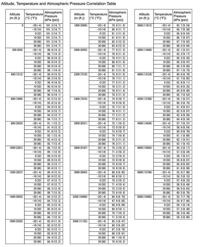
Enter the following menus: Powertrain / Engine / Data List / Atmospheric Pressure.
Powertrain > Engine > Data ListTester Display Atmospheric Pressure -
Using the table, read the normal atmospheric pressure value for the applicable altitude and temperature.
Tech Tips
-
Standard atmospheric pressure is approximately 101 kPa(abs) [14.65 psi(abs)].
-
For every 100 m (328 ft.) increase in altitude, atmospheric pressure drops by approximately 1 kPa [0.15 psi]. This varies by weather.
-
-
Compare the Atmospheric pressure value in the Data List with the normal atmospheric value from the table.
Result Result Proceed to Other than the following A Difference between Atmospheric Pressure in the Data List and normal atmospheric pressure value is 10 kPa (1.45 psi) or more. B
B
REPLACE ECM Click here
A
-
-
CLEAR DTC
-
Connect the GTS to the DLC3.
-
Turn the engine switch on (IG).
-
Turn the GTS on.
-
Clear the DTCs.
Powertrain > Engine > Clear DTCs -
Turn the engine switch off and wait for at least 30 seconds.
Result Proceed to NEXT
NEXT
-
-
READ OUTPUT DTC
-
Remove the vacuum sensor assembly, switch bank 1 and bank 2, and then install the vacuum sensor assembly.
-
Drive the vehicle in accordance with the driving pattern described in Confirmation Driving Pattern.
-
Enter the following menus: Powertrain / Engine / Trouble Codes.
-
Read the DTCs.
Powertrain > Engine > Trouble CodesResult Result Proceed to A bank DTC different from the one shown in step 1 is output A Other than above B
A
REPLACE VACUUM SENSOR ASSEMBLY Click here
B
-
-
CHECK HARNESS AND CONNECTOR (VACUUM SENSOR ASSEMBLY - ECM)
-
Disconnect the vacuum sensor assembly connector.
-
Disconnect the ECM connector.
-
Measure the resistance according to the value(s) in the table below.
Standard Resistance Tester Connection Condition Specified Condition D44-3 (VC) - D1-96 (VCPR) Always Below 1 Ω D44-2 (PIC) - D1-124 (PIC) Always Below 1 Ω D44-1 (E2) - D1-97 (EPR) Always Below 1 Ω D45-3 (VC2) - D1-96 (VCPR) Always Below 1 Ω D45-2 (PIC2) - D1-123 (PIC2) Always Below 1 Ω D45-1 (E22) - D1-97 (EPR) Always Below 1 Ω D44-3 (VC) or D1-96 (VCPR) - Body ground and other terminals Always 10 kΩ or higher D44-2 (PIC) or D1-124 (PIC) - Body ground and other terminals Always 10 kΩ or higher D45-3 (VC2) or D1-96 (VCPR) - Body ground and other terminals Always 10 kΩ or higher D45-2 (PIC2) or D1-123 (PIC2) - Body ground and other terminals Always 10 kΩ or higher Result Proceed to OK NG
OK
REPLACE ECM Click here
NG
REPAIR OR REPLACE HARNESS OR CONNECTOR
-
-
CHECK INTAKE SYSTEM
-
Check that there is no air suction or blockage at any points in the intake system.
OK No air suction or blockage. Tech Tips
Perform "Inspection After Repair" after repairing or replacing the intake system.
Result Proceed to OK NG
NG
REPAIR OR REPLACE INTAKE SYSTEM
OK
-
-
READ VALUE USING GTS (MAF SENSOR)
-
Connect the GTS to the DLC3.
-
Start the engine.
-
Turn the GTS on.
-
Allow the engine to idle until Coolant Temperature reaches 75°C (167°F) or higher.
-
Enter the following menus: Powertrain / Engine / Data List / MAF Sensor Bank1 and MAF Sensor Bank2.
Powertrain > Engine > Data ListTester Display MAF Sensor Bank1 MAF Sensor Bank2 -
Read Mass Air Flow Sensor with the engine speed at 3000 rpm.
Standard GTS Display Condition Specified Condition MAF Sensor Bank1 Engine warmed up
Park (P) selected
A/C: Off
Engine Speed: 3000 rpm
Between 6.5 and 30.0 gm/sec MAF Sensor Bank2 Between 6.5 and 30.0 gm/sec Result Proceed to OK NG
NG
CHECK HARNESS AND CONNECTOR Click here
OK
-
-
INSPECT VACUUM SENSOR ASSEMBLY
-
Inspect the vacuum sensor assembly.
Result Proceed to OK NG
NG
CHECK HARNESS AND CONNECTOR Click here
OK
-
-
CLEAR DTC
-
Connect the GTS to the DLC3.
-
Turn the engine switch on (IG).
-
Turn the GTS on.
-
Clear the DTCs.
Powertrain > Engine > Clear DTCs -
Turn the engine switch off and wait for at least 30 seconds.
Result Proceed to NEXT
NEXT
-
-
CHECK WHETHER DTC OUTPUT RECURS (DTC P006D62 AND/OR P00F762)
-
Drive the vehicle in accordance with the driving pattern described in Confirmation Driving Pattern.
-
Enter the following menus: Powertrain / Engine / Utility / All Readiness.
Powertrain > Engine > UtilityTester Display All Readiness -
Input the DTC: P006D62 and/or P00F762.
-
Check the DTC judgment result.
Result Result Proceed to NORMAL
(DTCs are not output)
A ABNORMAL
(DTC P006D62 and/or P00F762 is output)
B
A
END
B
REPLACE ECM Click here
-
-
CHECK HARNESS AND CONNECTOR
-
Disconnect the vacuum sensor assembly connector.
-
Turn the engine switch on (IG).
-
Measure the voltage according to the value(s) in the table below.
Standard Voltage Tester Connection Condition Specified Condition D44-3 (VC) - D44-1 (E2) Engine switch on (IG) 4.5 to 5.5 V D45-3 (VC2) - D45-1 (E22) Engine switch on (IG) 4.5 to 5.5 V D44-2 (PIC) - D44-1 (E2) Engine switch on (IG) 3.0 to 5.5 V D45-2 (PIC2) - D45-1 (E22) Engine switch on (IG) 3.0 to 5.5 V -
Turn the engine switch off and wait for at least 30 seconds.
-
Measure the resistance according to the value(s) in the table below.
Standard Resistance Tester Connection Condition Specified Condition D44-3 (VC) - D44-2 (PIC) Engine switch off 171 to 189 kΩ D45-3 (VC2) - D45-2 (PIC2) Engine switch off 171 to 189 kΩ D44-1 (E2) - Body ground Always Below 1 Ω D45-1 (E22) - Body ground Always Below 1 Ω Result Proceed to OK NG
OK
REPLACE VACUUM SENSOR ASSEMBLY Click here
NG
-
-
CHECK HARNESS AND CONNECTOR (VACUUM SENSOR ASSEMBLY - ECM)
-
Disconnect the vacuum sensor assembly connector.
-
Disconnect the ECM connector.
-
Measure the resistance according to the value(s) in the table below.
Standard Resistance Tester Connection Condition Specified Condition D44-3 (VC) - D1-96 (VCPR) Always Below 1 Ω D44-2 (PIC) - D1-124 (PIC) Always Below 1 Ω D44-1 (E2) - D1-97 (EPR) Always Below 1 Ω D45-3 (VC2) - D1-96 (VCPR) Always Below 1 Ω D45-2 (PIC2) - D1-123 (PIC2) Always Below 1 Ω D45-1 (E22) - D1-97 (EPR) Always Below 1 Ω D44-3 (VC) or D1-96 (VCPR) - Body ground and other terminals Always 10 kΩ or higher D44-2 (PIC) or D1-124 (PIC) - Body ground and other terminals Always 10 kΩ or higher D45-3 (VC2) or D1-96 (VCPR) - Body ground and other terminals Always 10 kΩ or higher D45-2 (PIC2) or D1-123 (PIC2) - Body ground and other terminals Always 10 kΩ or higher Result Proceed to OK NG
OK
REPLACE ECM Click here
NG
REPAIR OR REPLACE HARNESS OR CONNECTOR
-
-
CHECK HARNESS AND CONNECTOR
-
Disconnect the mass air flow meter sub-assembly connector.
-
Turn the engine switch on (IG).
-
Measure the voltage according to the value(s) in the table below.
Standard Voltage Tester Connection Condition Specified Condition D17-3 (VCCR) - D17-2 (E2GR) Engine switch on (IG) 4.8 to 5.2 V D17-1 (FGR) - D17-2 (E2GR) Engine switch on (IG) 4.8 to 5.2 V D16-3 (VCC) - D16-2 (E2G) Engine switch on (IG) 4.8 to 5.2 V D16-1 (FG) - D16-2 (E2G) Engine switch on (IG) 4.8 to 5.2 V -
Turn the engine switch off and wait for at least 30 seconds.
-
Measure the resistance according to the value(s) in the table below.
Standard Resistance Tester Connection Condition Specified Condition D17-3(VCCR) - D17-1(FGR) Engine switch off 2.09 to 2.31 kΩ D16-3(VCC) - D16-1(FG) Engine switch off 2.09 to 2.31 kΩ D17-2(E2GR) - Body ground Always Below 1 Ω D16-2(E2G) - Body ground Always Below 1 Ω Tech Tips
Perform "Inspection After Repair" after replacing the mass air flow meter sub-assembly.
Result Proceed to OK NG
OK
REPLACE MASS AIR FLOW METER SUB-ASSEMBLY Click here
NG
-
-
CHECK HARNESS AND CONNECTOR (MASS AIR FLOW METER SUB-ASSEMBLY - ECM)
-
Disconnect the mass air flow meter sub-assembly connector.
-
Disconnect the ECM connector.
-
Measure the resistance according to the value(s) in the table below.
Standard Resistance Tester Connection Condition Specified Condition D17-3 (VCCR) - D1-107 (VCVG) Always Below 1 Ω D17-1 (FGR) - D1-82 (VG) Always Below 1 Ω D17-2 (E2GR) - D1-84 (E2G) Always Below 1 Ω D16-3 (VCC) - D1-107 (VCVG) Always Below 1 Ω D16-1 (FG) - D1-80 (VG2) Always Below 1 Ω D16-2 (E2G) - D1-84 (E2G) Always Below 1 Ω D17-3 (VCCR) or D1-107 (VCVG) - Body ground and other terminals Always 10 kΩ or higher D17-1 (FGR) or D1-82 (VG) - Body ground and other terminals Always 10 kΩ or higher D16-3 (VCC) or D1-107 (VCVG) - Body ground and other terminals Always 10 kΩ or higher D16-1 (FG) or D1-80 (VG2) - Body ground and other terminals Always 10 kΩ or higher Result Proceed to OK NG
OK
REPLACE ECM Click here
NG
REPAIR OR REPLACE HARNESS OR CONNECTOR
-