ECD SYSTEM(w/ Glow Plug Controller) DATA LIST / ACTIVE TEST
DATA LIST
Tip:Using the GTS to read the Data List allows the values or states of switches, sensors, actuators and other items to be read without removing any parts. This non-intrusive inspection can be very useful because intermittent conditions or signals may be discovered before parts or wiring is disturbed. Reading the Data List information early in troubleshooting is one way to save diagnostic time.
Note:In the following table, the values listed under "Normal Condition" are reference values. Do not depend solely on these reference values when deciding whether a part is faulty or not.
Tip:When reading values of the Data List, confirm that PM regeneration is not activated (value of "After Injection Period" is 0) by entering the following menus: Powertrain / Engine and ECT / Data List / After Injection Period.
If PM regeneration is activated (value of "After Injection Period" is not 0), drive the vehicle until PM regeneration is complete (value of "After Injection Period" becomes 0).
When idling, EGR cut occurs under either of the following conditions:
-
PM regeneration is activated.
Idling time is long (approximately 20 minutes or more).
If EGR is cut off when idling and PM regeneration is not activated, when the vehicle is driven in 4th gear between 90 and 100 km/h (56 and 62 mph) for 30 minutes, EGR resumes.
Warm up the engine.
Turn the ignition switch off.
Connect the GTS to the DLC3.
Turn the ignition switch to ON.
Start the engine.
Turn the GTS on.
Enter the following menus: Powertrain / Engine and ECT / Data List.
Tip:To display the list box, press the pull down menu button next to Primary. Then select a measurement group.
When you select a measurement group, the ECU data belonging to that group is displayed.
Measurement Group List / Description
-
All Data / All data
Primary / -
Engine Control / Engine control system related data
Diesel General / General data to analyze engine conditions for diesel engine
Common Rail / Fuel system related data
Common Rail (All) / Fuel system related detailed data
Diesel EGR / EGR system related data
Diesel Throttle / Diesel throttle system related data
VN Turbo / VN turbo related data
Diesel Exhaust / Exhaust control system related data
Diesel Starting / "Difficult to start" related data
Diesel Rough Idle / "Rough idle" related data
Diesel Lack of Power / "Lack of power" related data
Diesel Knocking / "Knocking" related data
Diesel Black Smoke / "Black smoke" related data
Monitor Status / Monitor status related data
Charging Control / Charging control system related data
Compression / Data used during "Check the Cylinder Compression" in "Active Test"
AT / Automatic transmission system related data
Vehicle Information / Vehicle information
Catalytic Converter / Catalytic converter related data
Check the values by referring to the table below.
Tip:The title used for each group of Data List items in this repair manual does not appear on the GTS. However, the name in parentheses after the title, which is a Measurement Group, does appear on the GTS. When the name shown in parentheses is selected on the GTS, all the Data List items listed for that group will be displayed.
"Reference Value" is the assessment of one vehicle. Use it only for reference. Especially when the engine has been idling for a long time, the EGR valve, throttle motor and MAF values change. Do not depend solely on these reference values when deciding whether a part is faulty or not.
Various Vehicle Conditions 1 (All Data)
Powertrain > Engine and ECT > Data List
Tester Display
Measurement Item
Type
Range
Normal Condition
Reference Value
Diagnostic Note
Vehicle Speed
Vehicle speed
Sensor output (from combination meter)
Min.: 0km/h, Max.: 255 km/h
Actual vehicle speed
-
Cause of Out of Range:
Speed sensor
Speed sensor circuit
Engine Speed
Engine speed
Sensor output (crankshaft position sensor)
Min.: 0 rpm, Max.: 16383 rpm
Idling with warm engine: 720 to 820 rpm
Idling ("Coolant Temp" = 77°C [171°F]): 770 rpm
When the crankshaft position sensor is malfunctioning, "Engine speed" is approximately 0 or varies greatly from the actual engine speed.
Cause of Out of Range:
Crankshaft position sensor
Crankshaft position sensor circuit
Calculate Load
Calculated load by ECM
Calculated value by ECM
Min.: 0%, Max.: 100%
Idling with warm engine: 10 to 35%
Running without load (2500 rpm): 10 to 35%
Driving with the accelerator fully open at 3000 rpm: 80 to 100%
Ignition switch ON: 0.0%
Cranking (243 rpm): 49.4%
Idling (engine warmed up): 18.0% (2 minutes after starting the engine)
Running without load (2500 rpm): 20.7%
Running without load (4000 rpm): 24.3%
Calculate load = (Actual inner torque / Full inner torque) x 100.
Cause of Out of Range:
Malfunction in which turbo pressure or Mass Air Flow (MAF) decreases
MAF
Air flow rate from MAF meter
Sensor output (MAF meter)
Min.: 0 gm/sec, Max.: 655.35 gm/sec
Idling (EGR valve open): 3 to 7 gm/sec
Idling (EGR valve closed): 7 to 11 gm/sec
Running without load (2000 rpm): 10 to 40 gm/sec
Ignition switch ON: 0.00 gm/sec
Cranking (243 rpm): 3.86 gm/sec
Idling (engine warmed up): 8.88 gm/sec
Running without load (2500 rpm): 34.86 gm/sec
Running without load (4000 rpm): 55.55 gm/sec
Based on the MAF, the ECM controls the fuel injection volume, injection timing, EGR, etc.
If the MAF value exceeds the normal condition when the engine is idling, the EGR passage may possibly be clogged.
Tip:If the time of engine idling is long (approximately 20 minutes or more), EGR will be cut off. At this time, if the vehicle is driven in 4th gear between 90 and 100 km/h (56 and 62 mph) for 30 minutes, EGR resumes.
Cause of Out of Range:
Mass air flow meter
Mass air flow meter circuit
Intake related clog or leak
Exhaust related clog
Turbocharger sub-assembly
Leak or clog in passages for turbocharger
Malfunction in which electric EGR control valve assembly does not close
Symptoms when out of range:
Rough idling
Atmosphere Pressure
Atmospheric pressure value
Sensor output (atmospheric pressure sensor [built into ECM])
Min.: 0 kPa, Max.: 255 kPa
Actual atmospheric pressure
Ignition switch ON: 99 kPa
At the ignition switch ON or just after the ignition switch OFF, then the difference between the atmospheric pressure sensor and turbo pressure sensor output is 25 kPa or higher, there is a malfunction in one of the sensors.
Standard atmospheric pressure: 101 kPa(abs) [758 mmHg(abs)].
For every 100 m increase in altitude, pressure drops by 1 kPa (7.5 mmHg).
Value varies with by weather (high atmospheric pressure, low atmospheric pressure).
Cause of Out of Range:
Atmospheric pressure sensor itself has failed (atmospheric pressure sensor is inside the ECM)
MAP
Absolute pressure inside intake manifold
Sensor output (diesel turbo pressure sensor)
Min.: 0 kPa, Max.: 255 kPa
Idling: 90 to 105 kPa (depending on barometric pressure)
Engine running without load at 3000 rpm: 110 to 150 kPa
Ignition switch ON: 98 kPa
Cranking: 98 kPa
Idling (engine warmed up): 98 kPa (2 minutes after starting the vehicle)
Running without load (2500 rpm): 122 kPa
Running without load (3000 rpm): 127 kPa
Running without load (4000 rpm): 144 kPa
When the ignition switch is ON or the vehicle is idling, the intake manifold absolute pressure and atmospheric pressure are approximately the same (standard atmospheric pressure = 101 kPa).
Above approximately 1500 rpm, the turbo becomes effective, and the pressure becomes higher than atmospheric pressure.
Inspect while comparing with "Target Booster Pressure".
With the accelerator fully open, if the MAP (intake manifold absolute pressure) is low compared to the target booster pressure by at least 15 kPa for 5 seconds or more, a feeling of insufficient power will occur.
Cause of Out of Range:
Diesel turbo pressure sensor
Intake related clog or leak
Exhaust related clog
Turbocharger sub-assembly
Leak or clog in passages for turbocharger
Electric EGR control valve assembly stuck open
Exhaust leak
Throttle valve stuck closed
Symptoms when out of range:
Lack of power
Coolant Temp
Engine coolant temperature
Sensor output (engine coolant temperature sensor)
Min.: -40°C, Max.: 140°C
After warming up engine: 75 to 100°C (167 to 212°F)
After warming up engine: 75°C (167°F)
After a long soak, the engine coolant temperature, intake air temperature, and intake air temperature after intercooler are approximately equal.
If the value is -30°C (-22°F), or 120°C (248°F) or higher, the sensor circuit is open or shorted.
Cause of Out of Range:
Engine coolant temperature sensor
Symptoms when out of range:
Difficult starting when engine is cold, rough idle, black smoke, lack of power
Intake Air
Intake air temperature
Sensor output (intake air temperature sensor [built into MAF meter])
Min.: -40°C, Max.: 140°C
Equivalent to temperature at intake manifold
Idling: 27°C (81°F)
After a long soak, the engine coolant temperature, intake air temperature, and intake air temperature after intercooler are approximately equal.
If the value is -40°C (-40°F), or 120°C (248°F) or higher, the sensor circuit is open or shorted.
Cause of Out of Range:
Intake air temperature sensor
Intake Air Temp (Turbo) Supported
Status of intake air temperature after intercooler supported
-
Unsupp or Supp
Supp
-
-
Intake Air Temp (Turbo)
Intake air temperature after intercooler
Sensor output (intake air temperature sensor after intercooler)
Min.: -40°C, Max.: 215°C
70°C (158°F) or less
Idling: 46°C (115°F)
After a long soak, the engine coolant temperature, intake air temperature, and intake air temperature after intercooler are approximately equal.
If the value is -30°C (-22°F) or less, or 150°C (302°F) or higher, the sensor circuit is open or shorted.
Cause of Out of Range:
Decreased cooling efficiency of intercooler (contamination, clogging)
Engine Run Time
Engine run time
ECM calculations (using the engine speed)
Min.: 0 s, Max.: 65535 s
Time after the ignition switch turned to ON
-
Time elapsed since the DTCs were cleared (or shipment from the factory).
Initial Engine Coolant Temp
Initial engine coolant temperature
Sensor output when engine started
Min.: -40°C, Max.: 119.3°C
Engine coolant temperature when engine started
-
For Freeze Frame Data, this tells whether the malfunction happened during a cold start or with a warm engine.
Initial Intake Air Temp
Initial intake air temperature
Sensor output when engine started
Min.: -40°C, Max.: 119.3°C
Intake air temperature when engine started
-
-
Battery Voltage
Battery voltage
-
Min.: 0 V, Max.: 65.535 V
Ignition switch ON: 11 to 14 V
Ignition switch ON: 12.080 V
Idling: 13.980 V
If 11 V or less, characteristics of some electrical components change.
Symptoms when out of range:
If 5 V or less, starting becomes difficult
Alternate Duty Ratio
Alternator generation duty ratio
-
Min.: 0%, Max.: 127%
0 to 100%
-
Outputs the alternator generation duty in order to see the electrical load.
Can be used to determine whether a higher than normal injection volume at idle, etc. is resulting from electrical load or from some other source. For example, when the duty is not high but the idling injection volume is high, there is injector volume degradation or high engine friction.
Can be used for judging whether or not a malfunctioning component in the electrical system is generating continual generation requests (e.g., battery deterioration is causing an unending full recharge request, etc.). Regardless of whether or not an auxiliary device like the A/C or heater is active, if the alternator duty is always at MAX status, there is an electrical system abnormality, like battery deterioration.
Cause of Out of Range:
Battery deterioration
Alternator malfunction
Check for accessory lights, malfunctions, etc.
Pre Glow
Pre glow operation
Result of ECU calculations
ON or OFF
-
-
-
After Glow
After glow operation
Result of ECU calculations
ON or OFF
-
-
-
Eng Oil Press Switch Valve
Status of the engine oil pressure switching valve
Operation command
ON or OFF
-
-
This is the ECM command.
"ON" means that the engine oil pressure is being maintained at a low pressure.
Engine Oil Pressure
Engine oil pressure value
Sensor output (oil pressure sender gauge assembly)
Min.: 0 kPa, Max.: 1441.77 kPa
Idling (engine completely warmed up, A/C off and shift lever in neutral): 24.5 kPa or higher
Engine running at 3200 rpm (engine completely warmed up, A/C off and shift lever in neutral): 150 kPa or higher
The above values are valid for low pressure control mode when the engine oil temperature is 80°C (176°F). The values change depending on the temperature.
-
-
Accel Position
Accelerator position status
Calculated value by ECM
Min.: 0%, Max.: 100%
Accelerator pedal released:
0%
Accelerator pedal fully depressed:
100%
Ignition switch ON: 0.00% (accelerator pedal released)
Running without load (2500 rpm): 35.29%
Running without load (4000 rpm): 65.88%
"Accel Position" is the accelerator opening angle (%) for engine control use.
Accel Sens. No.1 Volt %
Accelerator position No. 1
-
Min.: 0%, Max.: 100%
-
-
-
Accel Sens. No.2 Volt %
Accelerator position No. 2
-
Min.: 0%, Max.: 100%
-
-
-
Throttle Control (Diesel Throttle)
Powertrain > Engine and ECT > Data List
Tester Display
Measurement Item
Type
Range
Normal Condition
Reference Value
Diagnostic Note
Target Throttle Position Supported
Status of target throttle position supported
-
Unsupp or Supp
Supp
-
-
Target Throttle Position
Target throttle position
Calculated value by ECM
Min.: 0%, Max.: 100%
Throttle valve fully closed: 0%
Throttle valve fully opened: 100%
Ignition switch ON: 100.0%
Cranking: 100.0%
Running without load (2500 rpm): 86.2%
Running without load (4000 rpm): 100.0%
Compare the target and actual throttle position values for troubleshooting a malfunction of the throttle actuator.
Target Throttle Position #2 Supported
Status of target throttle position No. 2 supported
-
Unsupp or Supp
Unsupp
-
-
Target Throttle Position #2
Target throttle position No. 2
Calculated value by ECM
Min.: 0%, Max.: 100%
-
-
-
Actual Throttle Position Supported
Status of actual throttle position supported
-
Unsupp or Supp
Supp
-
-
Actual Throttle Position
Actual throttle position
Calculated value by ECM
Min.: 0%, Max.: 100%
Idling: 20 to 100%
(Depending on atmospheric pressure, ambient temperature and engine temperature)
Ignition switch ON: 99.6%
Cranking: 0%
Running without load (2500 rpm): 86.6%
Running without load (4000 rpm): 100.0%
Soon after engine running to ignition switch off: 29.8% → 0.0% → 99.6%
Closing percentage of the throttle valve.
Fully closed: 0%.
Fully open: 100%.
Compare the target and actual throttle position values for troubleshooting a malfunction of the throttle actuator.
Symptoms when out of range:
Stuck closed: Engine stall, difficult to start, lack of power, black smoke, rough idle
Stuck open: Loud turbocharger sound, bad vibration when engine stopped
When ECM detects a malfunction of the diesel throttle (MIL on), engine power is restricted so that the vehicle can drive with a maximum speed of 80 to 120 km/h (49 to 74 mph).
Actual Throttle Position #2 Supported
Status of actual throttle position No. 2 supported
-
Unsupp or Supp
Unsupp
-
-
Actual Throttle Position #2
Actual throttle position No. 2
Calculated value by ECM
Min.: 0%, Max.: 100%
-
-
-
Throttle Motor DUTY
Diesel throttle motor actuator duty
Calculated value by ECM
Min.: 0%, Max.: 127.5%
-
Cranking (243 rpm): 14.5%
Running without load (2500 rpm): 15.0%
Running without load (4000 rpm): 13.5%
When the value of the Throttle Motor Duty increases, the moving force to open and close the diesel throttle valve increases.
Throttle Close Learning Val.
Throttle fully closed position learned value
-
Min.: 0 deg, Max.: 499.99 deg
13 to 21 deg
-
When the ignition switch is turned from ON to off and 5 seconds elapse, learning of "Throttle Close Learning Val." will be complete.
When "Throttle Close Learning Val." is outside of the normal range, a foreign object may be lodged in the throttle valve.
If the value is stuck at the upper limit of 21.25 deg, there is a chance that a malfunction is present. However, as the initial learned value is 21.25 deg, it is necessary to check the value after learning is completed.
Throttle Sensor Volt %
Throttle position sensor output voltage
Sensor output (throttle position sensor)
Min.: 0%, Max.: 100%
Throttle valve fully opened: 70 to 90%
Throttle valve fully closed: 10 to 20%
Ignition switch ON: 80.7%
Cranking: 80.7%
Running without load (2500 rpm): 71.7%
Running without load (4000 rpm): 80.7%
Throttle position sensor output voltage is converted using 5 V = 0%.
Fuel System (Common Rail (All))
Powertrain > Engine and ECT > Data List
Tester Display
Measurement Item
Type
Range
Normal Condition
Reference Value
Diagnostic Note
Injection Volume
Injection volume
Calculated value
Min.: 0 mm3/st, Max.: 1279.98 mm3/st
Idling: 2.0 to 8.0 mm3/st
Cranking (243 rpm): 0.00 mm3/st
Idling (engine warmed up): 3.98 mm3/st
Running without load (2500 rpm): 4.39 mm3/st
Running without load (4000 rpm): 5.99 mm3/st
Injection amount for each combustion cycle.
If Injector assemblies are clogged, fuel quality is poor, the fuel filter is clogged, or engine friction increases, then "Injection Volume" will increase.
Injection Feedback Val #1
Injection volume correction for No. 1 cylinder
Calculated value by ECM
Min.: -20 mm3/st, Max.: 19.8 mm3/st
Idling: -2.0 to 2.0 mm3/st
Idling: 0.0 mm3/st
#1 cylinder fuel cut (misfire): 3.59 mm3/st
When idling after warm up, the injection amount for each cylinder is corrected to optimize the difference between the engine speed of each cylinder.
Example: For cylinders that are slowing the engine speed compared to other cylinders, the injection volume is increased.
"Injection Feedback Val" more than 2.0 mm3/st: Injector breakdown is causing injection volume deviation, or insufficient compression is causing poor combustion.
Cause of Out of Range:
Injector assembly clogged
Injector assembly deterioration
Decrease in cylinder compression
Injector compensation code is incorrectly set (forgot to input code after replacement or made mistake during setting of code after replacing ECM with one from another vehicle)
Symptoms when out of range:
Rough idling, black smoke, white smoke, poor driveability, lack of power, abnormal combustion noise, difficult to start
Injection Feedback Val #2
Injection volume correction for No. 2 cylinder
Calculated value by ECM
Min.: -20 mm3/st, Max.: 19.8 mm3/st
Idling: -2.0 to 2.0 mm3/st
Idling: 0.0 mm3/st
#2 cylinder fuel cut (misfire): 3.59 mm3/st
Cause of Out of Range:
Injector assembly clogged
Injector assembly deterioration
Decrease in cylinder compression
Injector compensation code is incorrectly set (forgot to input code after replacement or made mistake during setting of code after replacing ECM with one from another vehicle)
Injection Feedback Val #3
Injection volume correction for No. 3 cylinder
Calculated value by ECM
Min.: -20 mm3/st, Max.: 19.8 mm3/st
Idling: -2.0 to 2.0 mm3/st
Idling: 0.0 mm3/st
#3 cylinder fuel cut (misfire): 3.59 mm3/st
Cause of Out of Range:
Injector assembly clogged
Injector assembly deterioration
Decrease in cylinder compression
Injector compensation code is incorrectly set (forgot to input code after replacement or made mistake during setting of code after replacing ECM with one from another vehicle)
Injection Feedback Val #4
Injection volume correction for No. 4 cylinder
Calculated value by ECM
Min.: -20 mm3/st, Max.: 19.8 mm3/st
Idling: -2.0 to 2.0 mm3/st
Idling: 0.0 mm3/st
#4 cylinder fuel cut (misfire): 3.59 mm3/st
Cause of Out of Range:
Injector assembly clogged
Injector assembly deterioration
Decrease in cylinder compression
Injector compensation code is incorrectly set (forgot to input code after replacement or made mistake during setting of code after replacing ECM with one from another vehicle)
Pilot 1 Injection Period
Pilot 1 injection period
Calculated value by ECM
Min.: 0 μs, Max.: 65535 μs
Idling: 200 to 400 μs
Cranking (243 rpm): 649 μs
Idling (engine warmed up): 304 μs
Running without load (2500 rpm): 230 μs
Running without load (4000 rpm): 217 μs
Check to see if "Pilot 1 Injection Period" is not 0 when the symptoms occur.
Symptoms when out of range:
Combustion noise, poor driveability, white smoke.
Pilot 2 Injection Period
Pilot 2 injection period
Calculated value by ECM
Min.: 0 μs, Max.: 65535 μs
Idling: 150 to 250 μs
Cranking (243 rpm): 431 μs
Idling (engine warmed up): 259 μs
Running without load (2500 rpm): 0 μs
Running without load (4000 rpm): 0 μs
Check to see if "Pilot 2 Injection Period" is not 0 when the symptoms occur.
Symptoms when out of range:
Combustion noise, poor driveability, white smoke.
Main Injection Period
Main injection period
Calculated value by ECM
Min.: 0 μs, Max.: 65535 μs
Idling: 200 to 600 μs
Cranking (243 rpm): 1453 μs
Idling (engine warmed up): 348 μs (2 minutes after starting the vehicle)
Running without load (2500 rpm): 286 μs
When the engine will not start, confirm that injection is performed.
Tip:As the engine stalls 1 minute after the MIL illuminates, freeze frame data cannot be checked.
After Injection Period
After injection period
Calculated value by ECM
Min.: 0 μs, Max.: 65535 μs
Except during PM / NOx / S regeneration: 0 μs
-
During PM regeneration, acceleration and deceleration shock may increase slightly.
Symptoms when out of range:
Poor drivability, white smoke during PM regeneration.
Pilot 1 Injection Timing
Pilot 1 injection timing
Calculated value
Min.: -210 deg(CA), Max.: 301.9 deg(CA)
Idling: -3.0 to 0.0 deg(CA)
-
Symptoms when out of range:
Combustion noise, poor drivability, white smoke.
Pilot 2 Injection Timing
Pilot 2 injection timing
Calculated value
Min.: -210 deg(CA), Max.: 301.9 deg(CA)
-3.0 to 0.0 deg(CA)
-
Symptoms when out of range:
Combustion noise, poor drivability, white smoke.
Main Injection Timing
Main injection timing
Calculated value
Min.: -210 deg(CA), Max.: 301.9 deg(CA)
Idling: -3.0 to 0.0 deg(CA)
-
Use "Main Injection Timing" to check poor drivability when the following symptoms are present: Bad injection timing, black smoke, and white smoke.
Symptoms when out of range:
Combustion noise, poor drivability, white smoke.
After Injection Timing
After injection timing
Calculated Value
Min.: -210 deg(CA), Max.: 301.9 deg(CA)
-
-
Symptoms when out of range:
Poor drivability, white smoke during PM regeneration.
Injection Pressure Correction
Injection pressure feedback compensation volume
Calculated Value
Min.: -640 mm3/st, Max.: 639.98 mm3/st
-
-
This indicator can be used for diagnosing supply pump related malfunctions.
When this value (absolute value) is large, it indicates that the difference between the actual and target fuel pressure is also large.
A positive value indicates that the pressure feed is being increased due to insufficient pressure. A negative value indicates that pressure is being reduced due to excessive rail pressure.
Target Common Rail Pressure Supported
Status of target common rail pressure supported
-
Unsupp or Supp
Supp
-
-
Target Common Rail Pressure
Target common rail pressure
Target common rail pressure (ECU calculated value)
Min.: 0 kPa, Max.: 655350 kPa
25000 to 185000 kPa: Engine running
Ignition switch ON: 30000 kPa
Cranking (243 rpm): 30000 kPa
Idling (engine warmed up): 30000 kPa (2 minutes after starting the vehicle)
Running without load (2500 rpm): 63150 kPa
Running without load (4000 rpm): 87460 kPa
Inspect the (actual) fuel pressure, comparing it against the common rail target value.
Considered normal when the actual fuel pressure is within +/-10000 kPa of the target fuel pressure under stable conditions.
Common Rail Pressure Supported
Status of common rail pressure supported
-
Unsupp or Supp
Supp
-
-
Common Rail Pressure
Common rail pressure
-
Min.: 0 kPa, Max.: 655350 kPa
Idling: 25000 to 35000 kPa
4000 rpm: 80000 to 120000 kPa
Common Rail Pressure = Target Common Rail Pressure +/-10000 kPa at stable condition
Ignition switch ON: 160 kPa
Idling (warm up the engine): 30960 kPa
Running without load (2500 rpm): 64190 kPa
Running without load (4000 rpm): 88380 kPa
Fuel pressure is the actual common rail fuel pressure.
Inspect by comparing the fuel pressure with the target fuel pressure.
When in a stable condition such as when idling, the fuel pressure is within +/-10000 kPa of the target fuel pressure.
The ECM uses fuel pressure for feedback control of the target fuel pressure via the supply pump.
The injection amount is determined based on the injection timing and fuel pressure.
Cause of Out of Range:
Supply pump assembly
High pressure pipes
Fuel pressure sensor
Injector assembly
Feed pump (supply pump assembly)
Fuel filter
Pressure control valve
Air in fuel line
Lack of fuel
Fuel Temperature Supported
Status of fuel temperature supported
-
Unsupp or Supp
Supp
-
-
Fuel Temperature
Fuel temperature
Sensor output (fuel temperature sensor)
Min.: -40°C, Max.: 215°C
Actual fuel temperature
Idling: 40°C (104°F)
After fully cold soaking, the fuel temperature is the same as the outside air temperature.
Target Pump SCV Current
Pump current target final value
Calculated value by ECM
Min.: 0 mA, Max.: 8191.8 mA
1530 mA or less
Cranking: 1070.0 mA
Idling: 1262.0 mA
Running without load (2500 rpm): 1389.0 mA
Running without load (4000 rpm): 1339.0 mA
ECM-calculated value for the suction control valve actuation target current.
Value is small when a high fuel pressure is desired.
Value becomes stuck at 1800 mA or more if operation is poor (poor movement due to deposits, etc.).
When this deviates from the standard value, it indicates that for some reason, even though the pump is running hard, the actual fuel pressure is inconsistent with the target fuel pressure.
Pressure Discharge Valve
Pressure control valve operation signal
-
ON or OFF
-
-
-
Air Fuel Ratio Control (All Data)
Powertrain > Engine and ECT > Data List
Tester Display
Measurement Item
Type
Range
Normal Condition
Reference Value
Diagnostic Note
AFS Current B1S1
Air fuel ratio sensor (for sensor 1) current
-
Min.: -128 mA Max.: 127.99 mA
-
-
-
AF Sensor Learning Value
Air fuel ratio sensor (for sensor 1) learning value
Calculated value by ECM
Min.: 0 V, Max.: 79.99 V
Idling: 2.2 to 3.2 V
-
Inspect the air fuel ratio sensor performance.
AF Sensor Learning Value B1S2
Air fuel ratio sensor (for sensor 2) learning value
Calculated value by ECM
Min.: 0 V, Max.: 79.99 V
Idling: 2.2 to 3.2 V
-
Inspect the air fuel ratio sensor performance.
EGR System (Diesel EGR)
Powertrain > Engine and ECT > Data List
Tester Display
Measurement Item
Type
Range
Normal Condition
Reference Value
Diagnostic Note
Target EGR Valve Pos Supported
Status of target EGR valve position supported
-
Unsupp or Supp
Supp
-
-
Target EGR Valve Pos
EGR valve target opening angle
ECU-calculated value based on sensors (MAF meter, turbo pressure sensor, intake air temperature (built into MAF meter), etc.)
Min.: 0%, Max.: 100%
Idling after engine warmed up: 0 to 100%
Ignition switch ON: 0.0%
Cranking: 0.0%
Idling with EGR off (engine warmed up): 0.0%
Running without load (2500 rpm): 0.0%
Running without load (4000 rpm): 0.0%
Fully open: 100%.
Fully closed: 0%.
Used for comparison to "Actual EGR Valve Pos".
Tip:If the time of engine idling is long (approximately 20 minutes or more), EGR will be cut off. At this time, if the vehicle is driven in 4th gear between 90 and 100 km/h (56 and 62 mph) for 30 minutes, EGR resumes.
Symptoms when out of range:
When value is out of range and approaching 0%: Mass air flow meter degradation, intake or exhaust system blockage
When value is out of range and approaching 100%: EGR pipe blockage
Target EGR Valve Pos #2 Supported
Status of target EGR valve position No. 2 supported
-
Unsupp or Supp
Unsupp
-
-
Target EGR Valve Pos #2
EGR valve target opening angle No. 2
ECU-calculated value based on sensors (MAF meter, turbo pressure sensor, intake air temperature (built into MAF meter), etc.)
Min.: 0%, Max.: 100%
-
-
-
Actual EGR Valve Pos Supported
Status of actual EGR valve position supported
-
Unsupp or Supp
Supp
-
-
Actual EGR Valve Pos
EGR valve position
Calculated from EGR valve opening position sensor
Min.: 0%, Max.: 100%
Idling after engine warmed up: 0 to 100%
Ignition switch ON: 0.0%
Cranking: 0.0%
Idling with EGR off (engine warmed up): 0.0%
Running without load (2500 rpm): 0.0%
Running without load (4000 rpm): 0.0%
Fully open: 100%.
Fully closed: 0%.
Inspect while comparing to "Target EGR Valve Pos".
Check the valve movement via the Active Test.
Sometimes the malfunction only occurs around a certain temperature, so refer to the engine coolant temperature and outside temperature at the time the malfunction occurred.
Tip:If the time of engine idling is long (approximately 20 minutes or more), EGR will be cut off. At this time, if the vehicle is driven in 4th gear between 90 and 100 km/h (56 and 62 mph) for 30 minutes, EGR resumes.
Symptoms when out of range:
EGR valve stuck open: Poor start (engine does not stop), black smoke, white smoke, lack of power
EGR valve stuck closed: Increased turbo booster noise
Actual EGR Valve Pos #2 Supported
Status of actual EGR valve position No. 2 supported
-
Unsupp or Supp
Unsupp
-
-
Actual EGR Valve Pos #2
EGR valve position No. 2
Calculated from EGR valve opening position sensor
Min.: 0%, Max.: 100%
-
-
-
EGR Position Sensor
EGR valve position sensor voltage
-
Min.: 0 V, Max: 4.999 V
EGR valve not open: 1.0 to 1.4 V
EGR valve open: 1.0 to 4.2 V
IG ON (EGR valve closed): 1.208 V
-
EGR Motor Duty #1
EGR valve motor duty ratio
-
Min.: 0%, Max.: 127.5%
0 to 100%
-
-
EGR Close Lrn. Val.
EGR fully closed position learned value
EGR valve position sensor value when EGR valve fully closed
Min.: 0 V, Max.: 4.999 V
0.7 to 1.7 V
Ignition switch ON: 1.208 V
This value is the EGR position sensor output voltage.
When the value is at the upper or lower limit of the normal range, it is possible that a foreign object is lodged in the EGR valve seat area.
As the lower and upper limits are 0 V and 1 V respectively, if the value becomes stuck at either of these values, there is a malfunction in the lift sensor or the valve position may be misaligned (foreign matter is present, etc.).
EGR Operation Prohibit
EGR Active Test operation prohibit
-
OK or NG
OK: Active Test item "Control the EGR Step Position" can be performed
-
OK: "EGR Valve Control Active Test Possible" Condition.
NG: "Not Possible" Condition.
EGR Cooler Bypass VSV
EGR cooler bypass valve VSV operation
-
ON or OFF
-
-
-
EGR Cooler Bypass Position
EGR cooler bypass valve position
-
OFF, Cooler, Half Pos or Bypass
Cooler or Bypass
-
-
Turbocharger Control 1 (VN Turbo)
Powertrain > Engine and ECT > Data List
Tester Display
Measurement Item
Type
Range
Normal Condition
Reference Value
Diagnostic Note
Target Booster Pressure Supported
Status of target boost pressure supported
-
Unsupp or Supp
Supp
-
-
Target Booster Pressure
Target boost pressure
Calculated value by ECM
Min.: 0 kPa, Max.: 2047.96 kPa
Idling: 90 to 110 kPa
3000 rpm without load: 120 to 160 kPa
4000 rpm without load: 120 to 190 kPa
Ignition switch ON: 100.96 kPa
Cranking: 100.96 kPa
Idling (engine warmed up): 100.96 kPa
Running without load (2500 rpm): 112.37 kPa
Running without load (4000 rpm): 145.87 kPa
Inspect while comparing with "MAP".
Symptoms when out of range:
Lack of power
VN Turbo Command Supported
Status of VN turbo command supported
-
Unsupp or Supp
Supp
-
-
Target VN Turbo Position
Target VN turbo position
Calculated value by ECM
Min: 0%, Max: 100%
IG ON: 80 to 100%
4000 rpm without load: 50 to 80%
IG ON: 89.8%
-
VN Turbo Command #2 Supported
Status of VN turbo command No. 2 supported
-
Unsupp or Supp
Unsupp
-
-
Target VN Turbo Position #2
Target VN turbo position No. 2
Calculated value by ECM
Min: 0%, Max: 100%
-
-
-
Actual VN Position Supported
Status of actual VN turbo position supported
-
Unsupp or Supp
Supp
-
-
Actual VN Turbo Position
Actual VN turbo position
-
Min.: 0%, Max.: 100%
0 to 100%
-
The actual VN turbo position is controlled to reach the target (Target VN Turbo Position).
Actual VN Position #2 Supported
Status of actual VN turbo position No. 2 supported
-
Unsupp or Supp
Unsupp
-
-
Actual VN Turbo Position #2
Actual VN turbo position No. 2
-
Min.: 0%, Max.: 100%
-
-
-
VN Close Learn Value
VN turbocharger closed learning value
-
Min.: 0 V, Max.: 4.999 V
1.0 to 2.0 V
-
-
VN Turbo Type
VN turbo type
-
Not Avl, Commo, Vacuum, CAN Com or DC
DC
-
-
Turbocharger Control 2 (All Data)
Powertrain > Engine and ECT > Data List
Tester Display
Measurement Item
Type
Range
Normal Condition
Reference Value
Diagnostic Note
VN Turbo Max Angle
VN turbo maximum opening angle
-
Min.: 0%, Max.: 127.5%
100%
-
-
VN Turbo Min Angle
VN turbo minimum opening angle
-
Min.: 0%, Max.: 127.5%
0%
-
-
Exhaust System (Diesel Exhaust)
Powertrain > Engine and ECT > Data List
Tester Display
Measurement Item
Type
Range
Normal Condition
Reference Value
Diagnostic Note
Exhaust Temperature B1S1 Supported
Status of exhaust gas temperature (bank 1 sensor 1) supported
-
Unsupp or Supp
Supp
-
-
Exhaust Temperature B1S1
Exhaust gas temperature of NSR (NOx Storage Reduction) catalyst
Sensor output (exhaust gas temperature sensor B1S1)
Min.: -40°C, Max.: 6513.5°C
Idling after engine warmed-up:
80 to 300°C (176 to 572°F)
During DPF catalyst regeneration:
200 to 600°C (392 to 1112°F)
Ignition switch ON: 50.0°C (122°F)
Idling (engine warmed up): 125.0°C (257°F)
Running without load (2500 rpm): 128.4°C (263°F)
Running without load (4000 rpm): 190.6°C (376°F)
If an open occurs in an exhaust temperature sensor circuit, 50°C (122°F) is displayed on the GTS. (engine warmed up)
If a short occurs in an exhaust temperature sensor circuit, 950°C (1742°F) is displayed on the GTS.
Cause of Out of Range:
Exhaust gas temperature sensor B1S1
Exhaust Temperature B1S2 Supported
Status of exhaust gas temperature (bank 1 sensor 2) supported
-
Unsupp or Supp
Supp
-
-
Exhaust Temperature B1S2
Exhaust gas temperature of DPF catalyst
Sensor output (exhaust gas temperature sensor B1S2)
Min.: -40°C, Max.: 6513.5°C
Idling after engine warmed-up:
80 to 300°C (176 to 572°F)
During DPF catalyst regeneration:
500 to 750°C (932 to 1382°F)
Ignition switch ON: 50.0°C (122°F)
Idling (engine warmed up): 138.4°C (281°F)
Running without load (2500 rpm): 125.0°C (257°F)
Running without load (4000 rpm): 153.5°C (308°F)
If an open occurs in an exhaust temperature sensor circuit, 50°C (122°F) is displayed on the GTS. (engine warmed up)
If a short occurs in an exhaust temperature sensor circuit, 950°C (1742°F) is displayed on the GTS.
Cause of Out of Range:
Exhaust gas temperature sensor B1S2
DPF catalyst deteriorated
Exhaust Temperature B1S3 Supported
Status of exhaust gas temperature (bank 1 sensor 3) supported
-
Unsupp or Supp
Unsupp
-
-
Exhaust Temperature B1S3
Exhaust gas temperature
Sensor output
Min.: -40°C, Max.: 6513.5°C
-
-
-
DPF Differential Pressure Supported
Status of DPF differential pressure supported
-
Unsupp or Supp
Supp
-
-
DPF Differential Pressure
DPF differential pressure sensor output
Sensor output (DPF differential pressure sensor)
Min.: -327.68 kPa, Max.: 327.67 kPa
Idling:
-3 to 3 kPa
-
When PM (Particulate Matter) builds up in the DPF catalyst, the "DPF Differential Pressure" value increases.
Cause of Out of Range:
DPF catalyst
DPF differential pressure sensor
Vacuum transmitting pipe clogged
Differential pressure sensor vacuum hose clogged
Catalyst Differential Press
Catalyst differential pressure
-
Min: -32.768, Max: 32.767
-0.1 to 1.0
Idling (warmed up engine): 0.03
-
Diff. Press. Sensor Corr.
Differential pressure sensor correction
-
Min: -327.68 kPa, Max: 327.67 kPa
-2.0 to 2.0 kPa
Idling (warmed up engine): -0.01 kPa
-
DPNR Status Reju (S)
Sulfur regeneration status
-
Standby, Ready, Operate or Compl
-
-
-
DPNR/DPF Status Reju(PM)
PM regeneration status
-
Standby, Ready, Operate or Compl
During DPF catalyst regeneration/
Operate
-
Standby
-
Before entering "Activate the DPF Rejuvenate (PM)"
Ready
-
Turn "Activate the DPF Rejuvenate (PM)" to on using the GTS but the enabling condition of the Active Test is not sufficient
Operate
-
PM regeneration is performing.
If "Activate the DPF Rejuvenate (PM)" is not finished completely, the status turns to Ready.
If "Activate the DPF Rejuvenate (PM)" is finished completely, the status turns to Compl.
Compl
-
PM regeneration is successfully completed (Amount of PM is 0 g)
Sulfur Accumulation Ratio
Sulfur accumuration ratio
-
Min: 0%, Max: 510%
-
-
-
PM Accumulation Ratio
PM accumulation ratio
-
Min.: 0%, Max.: 510%
0 to 173%
-
When catalyst regeneration is necessary, 118% is displayed for PM Accumulation Ratio. (Depending on the driving conditions, PM regeneration control will be performed automatically if the ratio exceeds 105%.)
Various Vehicle Conditions 2 (All Data)
Powertrain > Engine and ECT > Data List
Tester Display
Measurement Item
Type
Range
Normal Condition
Reference Value
Diagnostic Note
Starter Signal
Starter signal
-
ON or OFF
ON: Cranking
-
Ignition switch (START) output:
-
ON: Starter is operating.
OFF: Starter is not operating.
Cause of Out of Range:
OFF malfunction (ignition switch is turned to START but the starter signal is OFF and the starter is operating): Wire harness is open or shorted to ground
ON malfunction (ignition switch is off but the starter signal is ON and the starter is not operating): Wire harness is shorted to +B
Operation malfunction: Ignition switch malfunction, starter relay malfunction, starter malfunction, battery or battery cable is defective, or wire harness is open or shorted
Symptoms when out of range:
Ignition switch is ON but the starter does not operate: Starting is not possible
Clutch Switch
Clutch switch
Switch output (No. 2 clutch pedal switch assembly)
ON or OFF
ON: Clutch pedal depressed
-
When this item displays "OFF" with the clutch pedal depressed, the shock when accelerating and decelerating the vehicle becomes larger and pilot quality learning cannot be performed.
Symptoms when out of range:
When OFF with the clutch pedal depressed, the engine does not start.
Stop Light Switch
Stop light switch
Switch output (stop light switch)
ON or OFF
ON: Brake pedal depressed
OFF: Brake pedal released
-
Stop light switch (STP) operation condition:
-
ON: Light is on (Brake pedal is depressed).
OFF: Light is off (Brake pedal is released).
Cause of Out of Range:
OFF malfunction: Wire harness (stop light switch to ECM, stop light switch to +B) open or shorted to ground
ON malfunction: Wire harness (stop light switch to ECM) shorted to +B
Stop light switch assembly
Symptoms when out of range:
Stop light switch malfunction: DTC P0504 is stored
Shift Indication Enable
Shift indication enable
-
ON or OFF
-
-
-
A/C Signal
A/C (Air Conditioner) signal
A/C operation signal output from A/C amplifier
ON: Operating
OFF: Not operating
ON or OFF
ON: A/C on
-
Cause of Out of Range:
A/C switch
A/C amplifier
Wire harness or connector
Symptoms when out of range:
OFF malfunction (OFF even when A/C switch is turned on):
-
Engine speed decreases temporarily when the A/C is operating.
Immobiliser Communication
Immobiliser communication
-
ON or OFF
ON: Normal
-
Cause of Out of Range:
Use of a non-registered key
Key battery is fully depleted
ASL Switch
Speed limiter switch signal
Switch output (speed limiter switch)
ON or OFF
OFF: speed limiter switch off
ON: Speed limiter switch on
-
-
Test Result (Monitor Status)
Powertrain > Engine and ECT > Data List
Tester Display
Measurement Item
Type
Range
Normal Condition
Reference Value
Diagnostic Note
Complete Parts Monitor
Comprehensive component monitor
-
Not Avl or Avail
-
-
*
Fuel System Monitor
Fuel system monitor
-
Not Avl or Avail
-
-
*
Misfire Monitor
Misfire monitor
-
Not Avl or Avail
-
-
*
EGR/VVT Monitor
EGR/VVT monitor
-
Not Avl or Avail
-
-
*
EGR/VVT Monitor
EGR/VVT monitor
-
Compl or Incmpl
-
-
*
O2S(A/FS) Heater Monitor
O2S (A/FS) heater monitor
-
Not Avl or Avail
-
-
*
O2S(A/FS) Heater Monitor
O2S (A/FS) heater monitor
-
Compl or Incmpl
-
-
*
O2S(A/FS) Monitor
O2S (A/FS) monitor
-
Not Avl or Avail
-
-
*
O2S(A/FS) Monitor
O2S (A/FS) monitor
-
Compl or Incmpl
-
-
*
A/C Monitor
A/C monitor
-
Not Avl or Avail
-
-
*
A/C Monitor
A/C monitor
-
Compl or Incmpl
-
-
*
2nd Air Monitor
2nd air monitor
-
Not Avl or Avail
-
-
*
2nd Air Monitor
2nd air monitor
-
Compl or Incmpl
-
-
*
EVAP Monitor
EVAP monitor
-
Not Avl or Avail
-
-
*
EVAP Monitor
EVAP monitor
-
Compl or Incmpl
-
-
*
Heated Catalyst Monitor
Heated catalyst monitor
-
Not Avl or Avail
-
-
*
Heated Catalyst Monitor
Heated catalyst monitor
-
Compl or Incmpl
-
-
*
Catalyst Monitor
Catalyst monitor
-
Not Avl or Avail
-
-
*
Catalyst Monitor
Catalyst monitor
-
Compl or Incmpl
-
-
*
*:
Avail: The monitor is available on the vehicle.
Not Avl: The monitor is not available on the vehicle.
Incmpl / Compl: The item changes from Incmpl to Compl if the monitor was completed at least once at some time in the past. This item does not change when the ignition switch is turned off. However, the item changes back to Incmpl when DTCs are cleared or the battery cable is disconnected.
Various Vehicle Conditions 3 (All Data)
Powertrain > Engine and ECT > Data List
Tester Display
Measurement Item
Type
Range
Normal Condition
Reference Value
Diagnostic Note
TC Terminal
TC terminal status
-
ON or OFF
-
-
-
# Codes(Include History)
Number of codes
-
Min.: 0, Max.: 255
-
-
Number of DTCs appearing at least once during the last 40 times the engine was warmed up.
MIL
MIL status
-
ON or OFF
ON: MIL on
-
-
MIL ON Run Distance
MIL on run distance
Result of ECU calculations (using the vehicle speed)
Min.: 0 Km, Max.: 65535 Km
Distance traveled after DTC stored
-
Distance traveled after a DTC is stored.
Cleared when the negative (-) battery cable is disconnected or when the DTC is cleared using the GTS.
Running Time from MIL ON
Running time from MIL on
-
Min.: 0 min., Max.: 65535 min.
Running time after MIL turns on
-
Engine run time since the MIL illumination.
Cleared when the negative (-) battery cable is disconnected or when the DTC is cleared using the GTS.
Time after DTC Cleared
Time after DTC cleared
-
Min.: 0 min., Max.: 65535 min.
Time after DTCs cleared
-
Time elapsed since the DTCs were cleared (or shipment from the factory).
Distance from DTC Cleared
Distance after DTC cleared
-
Min.: 0 km, Max.: 65535 km
Distance driven after DTCs were cleared
-
Distance driven since the DTCs were cleared.
(Data List's "Distance from DTC cleared") - (Freeze frame data's "Distance from DTC cleared") = Distance driven since the abnormality occurred.
Warmup Cycle Cleared DTC
Warm-up cycle after DTC cleared
-
Min.: 0, Max.: 255
-
-
Number of engine warm-up since DTCs were cleared.
(Data List "Warmup Cycle Cleared DTC") - (Freeze frame data "Warmup Cycle Cleared DTC") = Warm-up cycles since the abnormality occurred.
IG OFF Elapsed Time
Time after engine switch off
-
Min.: 0 min, Max.: 655350 min
Cumulative time after engine switch off
-
-
OBD Requirements
OBD requirement
-
-
EOBD (Euro-OBD)
-
-
Number of Emission DTC
Number of emission DTCs
-
Min.: 0, Max.: 127
-
-
-
TC and TE1
TC and CG (TE1) terminals of DLC3
-
ON or OFF
-
-
-
Total Distance Traveled
Total distance traveled
-
Min.: 0 km, Max.: 16777215 km
-
-
-
Starting Control 1 (Diesel Starting)
Powertrain > Engine and ECT > Data List
Tester Display
Measurement Item
Type
Range
Normal Condition
Reference Value
Diagnostic Note
Engine Speed (Starter Off)
Engine speed when starter off
-
Min.: 0 rpm, Max.: 51199 rpm
-
-
This is the engine speed immediately after starting the engine.
Glow Request Lighting Time
Indicates the length of time the glow indicator light was on
-
Min.: 0 ms, Max.: 25500 ms
500 to 10000 ms
-
-
IG-ON Time
Elapsed time to start engine after the ignition switch was turned to ON
-
Min.: 0 ms, Max.: 25500 ms
-
-
This shows the condition when a glow plug turn turns on request occurred. If a malfunction occurred during a cold engine start (below 0°C [32°F]), based on IG-ON Time it can be determined whether the request was made after the glow plug and glow indicator turned off or not.
Lack of Power (Diesel Lack of Power)
Powertrain > Engine and ECT > Data List
Tester Display
Measurement Item
Type
Range
Normal Condition
Reference Value
Diagnostic Note
MAF Low
Status of mass air flow rate low
-
ON or OFF
OFF
-
When DTC P1608 is stored, this item indicates whether the cause of lack of power is related to the intake air amount.
This item indicates whether the intake air amount measured by the mass air flow meter was insufficient, which would cause the fuel injection volume to be reduced for a certain period of time. If this is the case, this item is ON and DTC P1608 is stored.
This item is ON when the intake air amount is low due to blockage in the intake system, disconnection of hoses or an excessive amount of EGR, and also when the intake amount is measured to be low due to deterioration of the mass air flow meter.
Symptoms when out of range:
Lack of power
Boost Pressure Low
Status of boost pressure Low
-
ON or OFF
OFF
-
When DTC P1608 is stored, this item indicates whether the cause of lack of power is due to the boost pressure.
This item indicates whether the actual boost pressure was insufficient compared to the target boost pressure, which would cause the fuel injection volume to be reduced for a certain period of time. If this is the case, this item is ON and DTC P1608 is stored.
Symptoms when out of range:
Lack of power
Engine Coolant Temp High
Status of engine coolant temperature high
-
ON or OFF
OFF
-
When DTC P1608 is stored, this item is indicates whether the cause of lack of power is due to high engine coolant temperature.
This item indicates whether the fuel injection volume was reduced for a certain period of time due to a high engine coolant temperature (overheating). If this is the case, item is ON and DTC P1608 is stored.
Symptoms when out of range:
Lack of power
MAF/Estimate MAF Ratio
Mass air flow rate (actual) / mass air flow rate (estimated) value
-
Min.: 0, Max.: 2.55
0.4 to 1.2
-
This item indicates the ratio of the intake air amount to the estimated intake air amount. The estimated air amount is calculated using the intake manifold pressure and intake air temperature.
When DTC P1608 is stored, this item is useful in determining whether there is a problem in the turbocharger system or a disconnected or leaking pipe in the high pressure intake system when boost pressure is insufficient.
When performing troubleshooting, this information is only valid when there is a high load (the diesel throttle is fully open) and the EGR system is off.
Rough Idle (Diesel Rough Idle)
Powertrain > Engine and ECT > Data List
Tester Display
Measurement Item
Type
Range
Normal Condition
Reference Value
Diagnostic Note
Rough Idle #1
Status of No. 1 cylinder rough idle
-
ON or OFF
OFF
-
This shows that the idle speed of this cylinder is lower than the other cylinders.
Rough Idle #2
Status of No. 2 cylinder rough idle
-
ON or OFF
OFF
-
This shows that the idle speed of this cylinder is lower than the other cylinders.
Rough Idle #3
Status of No. 3 cylinder rough idle
-
ON or OFF
OFF
-
This shows that the idle speed of this cylinder is lower than the other cylinders.
Rough Idle #4
Status of No. 4 cylinder rough idle
-
ON or OFF
OFF
-
This shows that the idle speed of this cylinder is lower than the other cylinders.
Starting Control 2 (All Data)
Powertrain > Engine and ECT > Data List
Tester Display
Measurement Item
Type
Range
Normal Condition
Reference Value
Diagnostic Note
Engine Starting Time
Time elapsed before engine starts (after starter turns on until engine speed reaches 400 rpm)
-
Min.: 0 ms, Max.: 655350 ms
-
-
This is the time elapsed after the starter turns on until the engine speed reaches 400 rpm.
This value is cleared 5 seconds after the engine is started and the value is displayed as 0 ms.
Engine Start Hesitation
History of hesitation during engine start
-
ON or OFF
-
-
This value changes to ON when the engine speed does not reach 500 rpm during cranking.
Low Rev for Eng Start
History of low engine speed after engine start
-
ON or OFF
-
-
This item changes to ON when the engine speed drops to 200 rpm or less within approximately 2 seconds of starting the engine.
Various Vehicle Conditions 4 (All Data)
Powertrain > Engine and ECT > Data List
Tester Display
Measurement Item
Type
Range
Normal Condition
Reference Value
Diagnostic Note
ACT VSV
A/C cut status for Active Test
-
ON or OFF
-
-
Active Test "Control the A/C Cut Signal" support data.
Electric Fan Motor
Electric fan motor operation
-
ON or OFF
-
-
-
Brake Override System
Brake override system status
-
ON or OFF
ON: Brake override system operating
-
-
Immobiliser Fuel Cut History
Status of immobiliser fuel cut
-
ON or OFF
OFF
-
If this item was ON when DTC P1604 was detected, this means that the engine could not start due to immobiliser operation.
Electrical Load Signal 1
Electrical load signal
-
ON or OFF
ON: Tail light on
-
-
Electrical Load Signal 2
Electrical load signal
-
ON or OFF
ON: Defogger switch on
-
-
Various Vehicle Conditions 5 (Vehicle Information)
Powertrain > Engine and ECT > Data List
Tester Display
Measurement Item
Type
Range
Normal Condition
Reference Value
Diagnostic Note
Model Code
Model code
-
-
-
-
Identifying model code: NDE18#
Engine Type
Engine type
-
-
-
-
Identifying engine type: 1NDTV
Cylinder Number
Cylinder number
-
Min.: 0, Max.: 255
-
-
Identifying cylinder number: 4
Transmission Type
Transmission type
-
-
-
-
Identifying transmission type: MT
Transmission Type2
Transmission type
-
-
NA
-
Unused
Destination
Destination
-
-
-
-
Identifying destination: W
Model Year
Model year
-
Min.: 1900, Max.: 2155
-
-
Identifying model year: 201#
System Identification
System identification
-
-
-
-
Identifying engine type: Diesel or Diesel&ECO
Compression (Compression)
Powertrain > Engine and ECT > Data List
Tester Display
Measurement Item
Type
Range
Normal Condition
Reference Value
Diagnostic Note
Engine Speed of Cyl #1
Engine speed for No. 1 cylinder
-
Min.: 0 rpm, Max.: 51199 rpm
"Engine speed" of all cylinders almost same
-
This is output only when Check the Cylinder Compression is performed using the Active Test.
The engine is cranked for approximately 10 seconds, then the speed of each cylinder is measured (compression test).
Indicates the speed of each cylinder when cranking. Example - Normal: Engine speed of all cylinders are approximately equal. When No. 1 cylinder compression is extremely low, "Engine speed of Cyl #1" is approximately 300 rpm, and "Engine speed of Cyl #2 to #4" is approximately 200 rpm.
Usually the GTS displays the value of when the engine is started.
Cause of Out of Range:
No. 1 cylinder compression goes down
Symptoms when out of range:
When the engine speed of all cylinders are not equal, idling will be rough.
Engine Speed of Cyl #2
Engine speed for No. 2 cylinder
-
Min.: 0 rpm, Max.: 51199 rpm
-
-
-
Engine Speed of Cyl #3
Engine speed for No. 3 cylinder
-
Min.: 0 rpm, Max.: 51199 rpm
-
-
-
Engine Speed of Cyl #4
Engine speed for No. 4 cylinder
-
Min.: 0 rpm, Max.: 51199 rpm
-
-
-
Av Engine Speed of All Cyl
Engine speed for all cylinders
-
Min.: 0 rpm, Max.: 51199 rpm
-
-
-
Tip:The speed of each cylinder can be measured (compression test) by using the GTS.
In the compression test, perform Active Test using GTS (Check the Cylinder Compression) and crank the engine for approximately 10 seconds. At this time, the speed of each cylinder is measured. If the speed of one cylinder is higher than the other cylinders, the compression pressure of that cylinder is determined to be lower than the other cylinders.
Warm up the engine.
Turn the ignition switch off.
Connect the GTS to the DLC3.
Turn the ignition switch to ON and turn the GTS on.
Enter the following menus: Powertrain / Engine and ECT / Active Test / Check the Cylinder Compression / Data List / Engine Speed of Cyl #1, Engine Speed of Cyl #2, Engine Speed of Cyl #3, Engine Speed of Cyl #4 and Av Engine Speed of All Cyl.
Push the snapshot button to turn the snapshot function on.
Tip:Using the snapshot function, data can be recorded during the Active Test.
While the engine is not running, press the RIGHT or LEFT button to Change the Cylinder Compression to ON.
Tip:After performing the above procedure, Check the Cylinder Compression will start. Fuel injection for all cylinders is prohibited and each cylinder engine speed measurement enters standby mode.
Crank the engine for about 10 seconds.
Monitor the engine speed (Engine Speed of Cyl #1 to #4, Av Engine Speed of All Cyl) displayed on the GTS.
Tip:After approximately 10 seconds of engine cranking, the engine speed measurement of each cylinder will change to the actual engine speed.
Note:Do not crank the engine continuously for 20 seconds or more.
If Check the Cylinder Compression needs to be performed after it is turned ON and performed once, press Exit to return to the Active Test menu screen. Then perform Check the Cylinder Compression again.
Use a fully-charged battery.
Stop cranking the engine, and then change Check the Cylinder Compression to OFF after the engine stops.
Note:If the Active Test is changed to OFF while the engine is being cranked, the engine will start.
Push the snapshot button to turn the snapshot function off.
Select the recorded data and display the data as a graph.
Check the change in engine speed values.
Various Vehicle Conditions 6 (AT)
Powertrain > Engine and ECT > Data List
Tester Display
Measurement Item
Type
Range
Normal Condition
Reference Value
Diagnostic Note
Shift SW Status (R Range)
Back-up light switch status
-
ON or OFF
ON: Shift lever in reverse position
-
-
MT Down Shift Indication
Manual transmission shift down indication
-
ON or OFF
-
-
-
MT Up Shift Indication
Manual transmission shift up indication
-
ON or OFF
-
-
-
Various Vehicle Conditions 7 (All Data)
Powertrain > Engine and ECT > Data List
Tester Display
Measurement Item
Type
Range
Normal Condition
Reference Value
Diagnostic Note
Stop&Start of Eng State
Engine status of stop and start system
-
IG, Run, Stopreq, Stop or Restart
-
-
-
ACTIVE TEST
Note:Do not perform the Active Test while stop and start control is being performed. (w/ stop and start system)
Tip:Using the GTS to perform Active Tests allows relays, VSVs, actuators and other items to be operated without removing any parts. This non-intrusive functional inspection can be very useful because intermittent operation may be discovered before parts or wiring is disturbed. Performing Active Tests early in troubleshooting is one way to save diagnostic time. Data List information can be displayed while performing Active Tests.
Connect the GTS to the DLC3.
Turn the ignition switch to ON.
Turn the GTS on.
Enter the following menus: Powertrain / Engine and ECT / Active Test.
Perform the Active Test.
Powertrain > Engine and ECT > Active Test
Tester Display
Measurement Item
Control Range
Diagnostic Note
Control the A/C Cut Signal
Control the A/C signal
ON/OFF
Test is possible when the following conditions are met:
Ignition switch ON
Engine stopped
Shift lever in neutral
Connect the TC and TE1
Turn on and off TC and CG (TE1) connection
ON/OFF
ON: TC and CG (TE1) are connected.
OFF: TC and CG (TE1) are disconnected.
Test is possible when the following conditions are met:
-
Ignition switch ON
Shift lever in neutral
Control the Electric Cooling Fan
Control the electric fan motor
ON/OFF
Test is possible when the following conditions are met:
Ignition switch ON
Engine stopped
Shift lever in neutral
Control the EGR Step Position
Control the EGR valve
1 to 100%
Test is possible when the following conditions are met:
Ignition switch ON
Engine stopped
Shift lever in neutral
Activate the DPF Rejuvenate (S)
Sulfur regeneration
ON/OFF
-
Activate the DPF Rejuvenate (PM)
DPF catalyst regeneration
ON/OFF
After clearing DTCs, immediately enter the Active Test / Activate the DPF Rejuvenate (PM), and then drive the vehicle.
Test the Fuel Leak
Pressurizes common rail internal fuel pressure, and checks for fuel leaks
Stop/Start
Perform inspection of the high pressure fuel system.
Test is possible when the following conditions are met:
Ignition switch ON
Engine running
Shift lever in neutral
Activate the EGR Valve Close
EGR valve control
Close/OFF
Test is possible when the following conditions are met:
Engine running
Engine warmed up
Shift lever in neutral
Activate the VSV for EGR Cooler Bypass
EGR cooler bypass valve VSV control
Bypass, OFF or Cooler
Test is possible when the following conditions are met:
Engine running
Engine warmed up
Shift lever in neutral
Note:Do not operate the EGR cooler bypass valve for 5 minutes or more during Active Test
Test the Turbo Charger Step Motor
Activate the turbocharger
0 to 60%
Test is possible when the following conditions are met:
Ignition switch ON
Engine stopped
Shift lever in neutral
Activate the VN Turbo Open
Turbocharger sub-assembly control
Open/OFF
Test is possible when the following conditions are met:
Ignition switch ON
Engine running
Shift lever in neutral
Diesel Throttle Target Angle
Control the diesel throttle valve
10 to 100%
Test is possible when the following conditions are met:
Ignition switch ON
Engine stopped
Shift lever in neutral
Control the Select Cylinder Fuel Cut
Cut off fuel injection from injector assembly
#1/#2/#3/#4
ON/OFF
Fuel injection is stopped while the test is ON.
Confirm that the vehicle is stopped and the engine is idling.
If the running condition of the engine does not worsen even though injection of the designated cylinder is stopped, the cylinder can be confirmed to be malfunctioning.
DTCs may be output after this Active Test. Make sure to check for DTCs after this Active Test. If any DTCs are output, make sure to clear them.
Check the Cylinder Compression
Check the cylinder compression pressure
ON/OFF
Fuel injection stops in all cylinders*
Tip:*: When cranking the engine, the Active Test measures the speed of each cylinder. In this Active Test, the fuel of all cylinders is cut when the engine is cranked for approximately 10 seconds.
At this time, the speed of each cylinder is measured. If the speed of one cylinder is higher than the other cylinders, the compression pressure of that cylinder is determined to be lower than the other cylinders.
Warm up the engine.
Turn the ignition switch off.
Connect the GTS to the DLC3.
Turn the ignition switch to ON.
Turn the GTS on.
Enter the following menus: Powertrain / Engine and ECT / Active Test / Check the Cylinder Compression.
Tip:To display the entire Data List, press the pull down menu button next to Primary. Then select Compression.
Push the snapshot button to turn the snapshot function on.
Tip:Using the snapshot function, data can be recorded during the Active Test.
While the engine is not running, press the ON button to change Check the Cylinder Compression to on.
Tip:After performing the above procedure, Check the Cylinder Compression will start. Fuel injection for all cylinders is prohibited and each cylinder engine speed measurement enters standby mode.
Crank the engine for about 10 seconds.
Monitor the engine speed (Engine Speed of Cyl #1 to #4) displayed on the GTS.
Tip:After approximately 10 seconds of engine cranking, the engine speed measurement of each cylinder will change to the actual engine speed.
Note:Do not crank the engine continuously for 20 seconds or more.
If it is necessary to crank the engine again after Check the Cylinder Compression has been changed to ON and the engine has been cranked once, press Exit to return to the Active Test menu screen. Then change Check the Cylinder Compression to ON and crank the engine.
Use a fully-charged battery.
Stop cranking the engine, and then change "Check the Cylinder Compression" to OFF after the engine stops.
Note:If the Active Test is changed to OFF while the engine is being cranked, the engine will start.
Push the snapshot button to turn the snapshot function off.
Select "Stored Data" on the GTS screen, select the recorded data and display the data as a graph.
Tip:If the data is not displayed as a graph, the change of the values cannot be observed.
Check the change in engine speed values.
SYSTEM CHECK
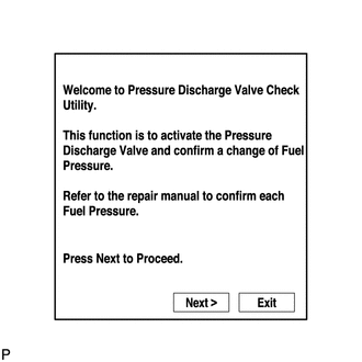
Activate the Pressure Discharge Valve Check
Tip:This procedure is for troubleshooting fuel pressure control malfunctions and combustion problems.
Malfunctions can be determined by checking the fuel pressure when performing fuel cut and operating the pressure control valve with the GTS.
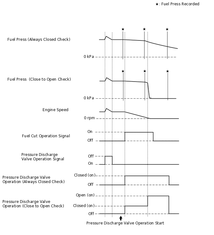
During "Pressure Discharge Valve Check", the GTS measures the fuel pressure while the engine is running, after the engine is stopped, and after the pressure control valve operates.
Connect the GTS to the DLC3.
Turn the ignition switch to ON.
-
Turn the GTS on.
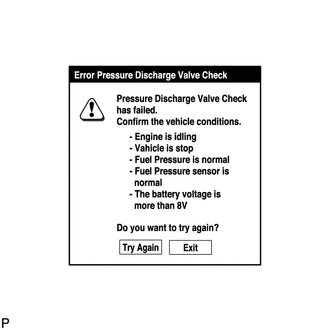
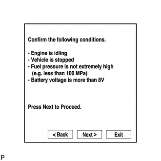
Note:Confirm the following conditions:
Engine is idling.
Vehicle is stopped.
Fuel pressure is not extremely high (less than 100000 kPa).
Fuel pressure sensor is normal.
Battery voltage is higher than 8 V.
Enter the following menus: Powertrain / Engine and ECT / Utility / Pressure Discharge Valve Check.
Powertrain > Engine and ECT > Utility
Tester Display
Pressure Discharge Valve Check
-
Press "Next".
-
Press "Next" again to proceed.
-
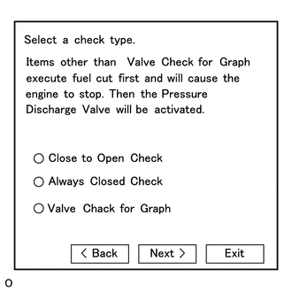
Select the check type "Valve Check for Graph".
Press "Next" again to proceed.
Press "Start" again to proceed.
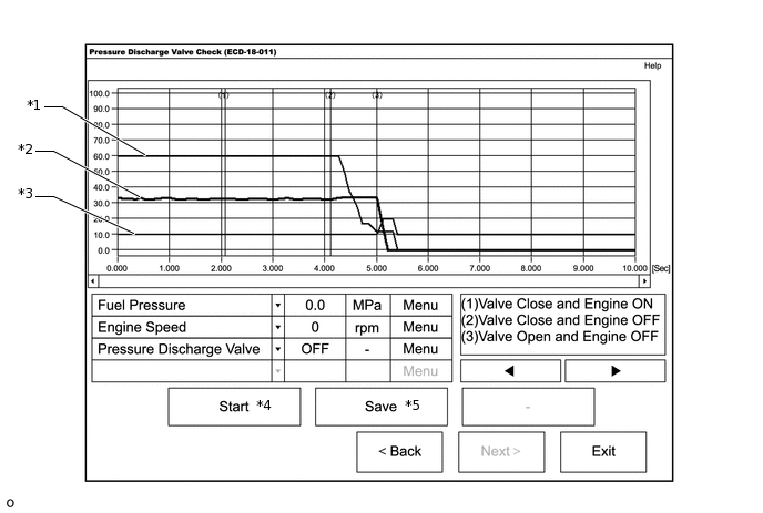
*1
Engine Speed
*2
Fuel Pressure
*3
Pressure Discharge Valve
-
-
*4: When "Start" is pressed, the pressure discharge valve check begins.
*5: If "Save" is pressed after the pressure discharge valve check, the data recorded during the valve check can be saved.
Select the check type "Close to Open Check" or "Always Closed Check".
Tip:"Close to Open Check" opens the pressure discharge valve after the engine stops.
"Always Closed Check" holds the pressure discharge valve closed during the check.
-
Press "Next".
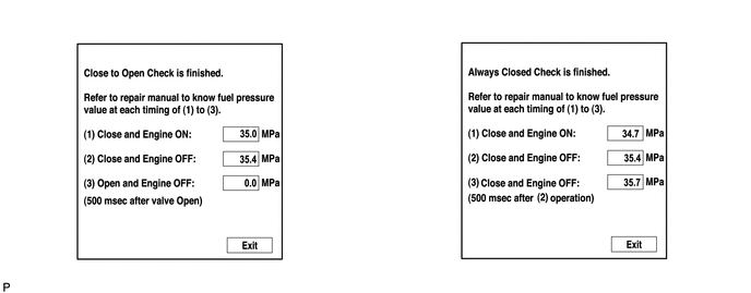
Perform troubleshooting based on the measurement results.
 Tip:
Tip:During "Close to Open Check", if there is no large change in fuel pressure when the pressure control valve is closed while the engine is running and after the engine is stopped, and if the value is approximately 0 kPa when the pressure control valve is open, the system is normal.
Perform "Always Closed Check" if the value is not 0 kPa when the pressure control valve is open during "Close to Open Check". If the results are the same as during "Close to Open Check", there is a pressure control valve operation malfunction.
If the fuel temperature is high, wait until the fuel temperature becomes the same as the ambient temperature before performing "Pressure Discharge Valve Check".
If a large amount of fuel is leaking, the fuel pressure decreases when the engine is stopped. However, the condition of the pressure control valve can still be determined by comparing the measurement results of "Close to Open Check" and "Always Closed Check".
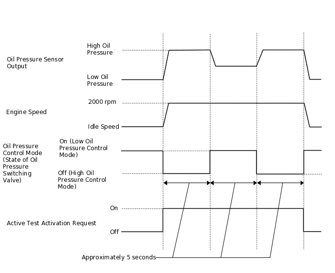
Engine Oil Pressure Control Check
Tip:Check whether the oil pressure control system is operating properly when the oil pressure switching valve is forcibly operated.
Perform this check when DTC P0524 is output.
Connect the GTS to the DLC3.
Turn the ignition switch to ON.
Turn the GTS on.
Start the engine and warm it up.
Tip:Confirm that the engine coolant temperature is between 70 and 90°C (158 and 194°F) after the engine is warmed up, as the oil pressure changes according to the engine coolant temperature.
Enter the following menus: Powertrain / Engine and ECT / Utility / Engine Oil Pressure Control Check.
Powertrain > Engine and ECT > Utility
Tester Display
Engine Oil Pressure Control Check
Note:Confirm the following conditions:
Engine is idling.
Vehicle is stopped.
Shift lever is in neutral.
Engine coolant temperature is in specified range.
Press "Next".
Tip:Even when the engine is warmed up, there are some instances where the oil pressure control system check cannot be performed.
The engine speed will increase during the oil pressure control system check.
Perform troubleshooting based on the measurement results.
Tip:The average oil pressure over 1 second when the valve is operated is displayed.
The engine oil pressure measured every 0.1 seconds is displayed on the detailed information screen.