CONTINUOUSLY VARIABLE TRANSAXLE SYSTEM Pattern Select Switch Sport Mode Circuit
| DTC Code | DTC Name |
|---|---|
| Pattern Select Switch Sport Mode Circuit |
DESCRIPTION
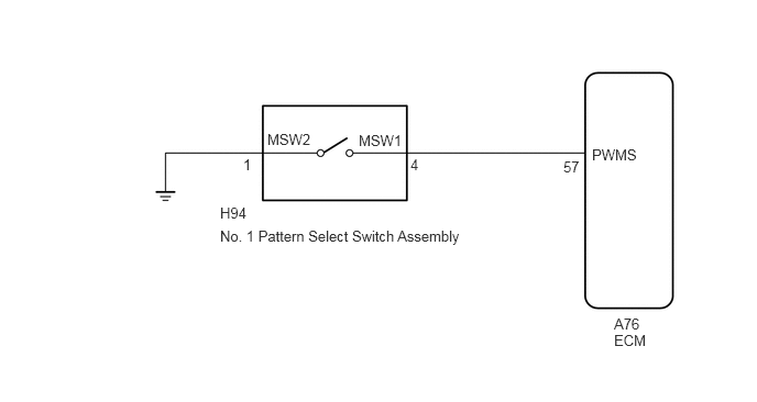
The ECM memory contains the programs for the normal and sport shift patterns.
By following the programs corresponding to the signals from the No. 1 pattern select switch assembly, the park/neutral position switch and other various sensors, the ECM switches the shift control solenoid valves on and off, and controls the transaxle gear ratio.
WIRING DIAGRAM
CAUTION / NOTICE / HINT
Perform initialization when parts related to the continuously variable transaxle are replaced (Click here).
Check that no DTCs are stored after performing initialization (Click here).
PROCEDURE
INSPECT NO. 1 PATTERN SELECT SWITCH ASSEMBLY
-
Remove the No. 1 pattern select switch assembly (Click here).
Measure the resistance according to the value(s) in the table below.
Standard Resistance
Tester Connection
Switch Condition
Specified Condition
4 (MSW1) - 1 (MSW2)
No. 1 pattern select switch on
Below 1 Ω
4 (MSW1) - 1 (MSW2)
No. 1 pattern select switch off
10 kΩ or higher
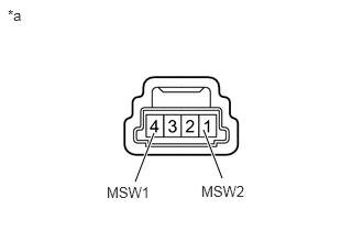
Table 1. Text in Illustration *a
Component without harness connected
(No. 1 Pattern Select Switch Assembly)
-
CHECK HARNESS AND CONNECTOR (NO. 1 PATTERN SELECT SWITCH ASSEMBLY - BODY GROUND)
-
Disconnect the No. 1 pattern select switch assembly connector.
Measure the resistance according to the value(s) in the table below.
Standard Resistance
Tester Connection
Condition
Specified Condition
H94-1 (MSW2) - Body ground
Always
Below 1 Ω
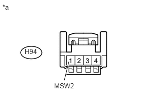
Table 2. Text in Illustration *a
Front view of wire harness connector
(to No. 1 Pattern Select Switch Assembly)
REPAIR OR REPLACE HARNESS OR CONNECTOR (NO. 1 PATTERN SELECT SWITCH ASSEMBLY - BODY GROUND)
-
CHECK HARNESS AND CONNECTOR (NO. 1 PATTERN SELECT SWITCH ASSEMBLY - ECM)
-
Disconnect the ECM connector.
Measure the resistance according to the value(s) in the table below.
Standard Resistance
Tester Connection
Switch Condition
Specified Condition
A76-57 (PWMS) - Body ground
No. 1 pattern select switch on
Below 1 Ω
A76-57 (PWMS) - Body ground
No. 1 pattern select switch off
10 kΩ or higher
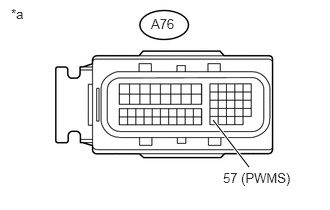
Table 3. Text in Illustration *a
Front view of wire harness connector
(to ECM)
REPAIR OR REPLACE HARNESS OR CONNECTOR
-
REPLACE ECM
Replace the ECM (Click here)